

The fundamental principles of power supplies is covered in the amplifiers chapter. This page assumes the basics are already known and only focuses on power supplies for valve amps.
Most valve amps are constructed on a pan chassis. The output transformer is rotated 90deg to avoid picking up the external AC magnetic field radiating from the I E core of the power transformer. A % of the AC magnetic field from the EI power transformer is induced into the chassis causing eddy currents. Chassis eddy currents are the major cause of hum problems in signal earthling.
This problem of hum induced eddy currents can be solved by having the amp and power supply on separate chassis. This solution would make the amp more expensive, including user inconvenience. There is no excuse for modern valve amps not to use C core or toroidal transformers.
Mono-block. If a choice is to be made to have 2 mono-blocks (2 separate mono valve amps for a stereo system) or a stereo amp on one chassis and a the power supply on a separate chassis. The power supply on a separate chassis solves the problem of the power transformer external magnetic field contaminating the valve amps electronics, whereas a mono-block does not.
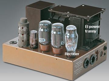
Rectifier. In the above pic the large valve at the right end corner of the chassis is the rectifier which converts AC from the power transformer to DC.
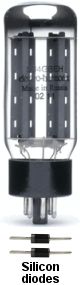 The 2 major limiting factors of early valve amps before the solid-state technology arrived was the valve rectifier and small electrolytic capacitors. When silicon diodes became available in 1960 almost every valve amp manufacturer used them. Also, whenever a valve amp needed servicing the valve rectifier was often replaced with silicon diodes. The rectifier valve was left in place (visual appearance) with its heater filament disconnected. The heater filament consumed 10W to 15W. Disconnecting the rectifier valve enabled the power transformer to run cooler and provide more current for the B+ supply.
Soggy. The rectifier valve has a high resistance in the forward direction, described by technicians as a soggy power supply. Cathode biased class A push-pull amps, B+ deregulation is not a problem because the current through the output valves is always at maximum and remains constant. But in class AB, the current through the output valves increases as the amp is turned up in level, the B+ supply would decrease, so far as to cause the output valves to be biased away from their linear position, resulting in increased distortion, particularly inter-modulation distortion.
Replacing the valve rectifier with 2 silicon diodes enables an amp to have a more stable B+ supply, but silicon diodes arrived before electrolytic capacitor technology had improved. A valve rectifier takes time to heat up which charges up the electrolytic capacitors slowly, protecting them. Early electrolytic capacitors could easily be damaged by being charged instantly with silicon diodes the moment the amp is turned on. A delayed soft turn on, using a relay, solves the diode inrush problem, but was rarely implemented.
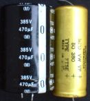
Electrolytic. Modern high quality electrolytic capacitors have approx x 10 greater capacitance, x 10 longer life and 105deg C rating, for a similar physical size. Modern high quality electrolytic capacitors can be instantly charged to full voltage with no detrimental effect. The old yellow electro is 50uF. The modern back electro is 470uF.
When occult audiophileism evolved during the 1980's, science and technology was replaced with mysticism and many occult followers believed the old rectifier valve and old electrolytic capacitors contributed to the magical sound of pre 1960 valve amps. Some valve amp manufacturers today, who cater to the occult market, use rectifier valves and old style electros.
Valve rectifier power supplies
Most early valve rectifier power supplies were full-wave capacitor input. Two half-wave rectifiers in opposite phase charge up the first electro to the peak of the pulsating DC. The peak of the pulsating DC wave is x 1.414 greater than the RMS. Only the peak of the pulsating DC voltage (10% of the available energy) charges the electro. Capacitor input supplies have poor regulation which means the B+ voltage drops significantly when a current load is applied.
The example power transformer in the below circuit has 2 x 350V AC windings in series. This can also be described as 700V AC with a centre tap that is connected to earth chassis, 350V AC + 350V AC = 700V AC. The valve rectifier has 2 anodes with a common cathode. Early electrolytic capacitors only had a small storage capacity. The first 20uF capacitor is charged up to the peak voltage of the pulsating DC, but because the electro is small there is a large amount of ripple. The inductance of the Pi filter choke must be very large to filter the excessive ripple. A Pi filter is a choke (non-saturable inductor) between 2 electros.
Rectifier valves were/are inefficient because of their high internal resistance. Also the 20uF is too small to maintain being fully charged during each of the DC peaks from the rectifier valve. The choke will average the pulsating DC peaks to a lower level to remove the ripple. A valve rectifier power supply with small electros has poor efficiency.
If the rectifier valve and small 20uF electros are replaced with silicon diodes and modern 470uF electros, the calculation for the B+ supply would closely follow the academic formula.
AC volts x 1.414 = DC V (B+)
360V AC x 1.414 = DC 509V (B+)
The B+ supply voltage from early valve rectifier power supplies drops as the output valves warm up and conduct current. Removing the output valves so no current is being taken from the power supply will cause the B+ voltage to rise close to the academic formula. 360V AC x 1.414 = 509V DC. Valve amps that use rectifier valves should not be turned on with the output valves removed. The electros can be over voltaged and damaged.
In the above circuit the valve rectifier inefficiency with small electros results in a loss of approx 70V from the academic calculation 509V to 440V when the output valves heat up and conduct current.
The majority of valve amps less than 40W are configured in class A push-pull (cathode bias). With cathode bias the quiescent current through the output valves is always at maximum, therefore constant. B+ stability (regulation) is not necessary. But in class AB the current through the output valves increases as the level increases, causing the B+ supply to be modulated by the changing current through the output valves.
6.3V AC Heaters. Most octal based output valve require approx 1.5A of current for the filament to heat the cathode. 4 output valves plus pre-amp valves and dial lights is approx 10A 60W total. 10A is a large amount of current and extra thick wire is required to connect the valve filaments. The large filament current creates an AC magnetic field around the wire which can be induced into the circuit components causing a constant annoying hummmmm.
The shortest path for heater wires should first go to the output valves, then the pre-amp valves. Heater wiring is put against the chassis and the circuit components above as far away as possible. A centre tap (CT) to earth from the 6.3V secondary winding is an attempt to minimise the AC magnetic field from the heater wires interfering with circuit components. Many power transformers have a separate 6.3V AC winding for the pre-amp valves.
Magnetic hum leakage from the valve filament can be induced into the cathode. Some high-end pre-amps have DC for the filaments of the phono pre-amp valve. Noval based valves 12AX7 etc can have the filaments in series 12.6V so only 1/2 the amount of current is required.
Choke input filter
The primary limitations of early valve rectifier power supplies was the high forward resistance in the rectifier valves and the small storage capacity of the electros (approx 20uF). 470uF electros are often used in high quality valve amps today.
Most valve amps above 40W are configured in class AB (negative bias). The quiescent current through each output valve is approx 50mA. When the amp is driven to full power the current can increase to approx 150mA. The B+ voltage from a traditional capacitor input supply will readily drop to a lower level. The B+ voltage will be modulated by the varying current through the output valves. As the B+ voltage reduces, so does the gain of the output valves. A modulating B+ voltage causes massive inter-modulation distortion.
Choke input filter power supplies, also referred to as swinging choke power supplies, are often seen in industrial electronics where a large amount of DC current is required with high regulation. Choke input filter supplies were often used in early valve rectifier power supplies for 100+W valve amps. The swinging choke is nearly as large as the power transformer. Two extra large valve rectifiers were often used. Each valve rectifier has the anodes in parallel to reduce its internal resistance, enabling greater current.
The pulsating DC from the rectifier valve goes through a large choke (non-saturable inductor). The swinging choke converts the pulsating DC to its RMS value without loosing energy. The internal losses in the 2 valve rectifiers is minimal. AC to DC conversion is close to the academic formula.
AC volts x 0.9 = DC volts
640V AC x 0.9 = 576V DC
A choke input power supply is approx 90% efficient, therefore the B+ will remain relatively stable when a class AB amp is driven at high power. In the above circuit, 16V loss is caused by the forward resistance of the 2 large valve rectifiers. 16V valve rectifier loss is small compared to B+ 560V.
The advantage of choke input supply is its excellent regulation and minimal pulsating DC ripple on the B+ voltage. In the earlier times when only small electros were available (20uF) increasing the inductance of the choke could directly compensate for the small value electros. A choke input filter using modern lager 470uF electros can achieve a close to perfect ripple free B+ supply.
CIP disadvantage. Choke input filter supply must have a load on it at all times for it to stabilise. Without a load, a choke input filter supply will behave as a capacitor input supply and the B+ voltage will raise to the peak of the pulsating DC voltage. In the example power supply, 640V AC x 1.414 = 904V DC. It is essential to have an external resistive load on the B+ output, at all times, or have a circuit that switches a resistive load onto the B+ if the amp is turned on without the output valves.
Swinging choke. The term "swinging choke" was often used to represent choke input filter supplies in valve amps. In industrial electronics the term swinging choke is used to represent the smallest physical size a choke can be to stabilise the DC current (requires further explanation). A large linear choke is normally used for valve amp power supplies, not a small swinging choke.
Negative bias (early)
In the previous above circuit, the -bias voltage is obtained from a 100V AC tap on the HT winding through a silicon diode 1/2 wave rectifier. The bias current is small and the DC ripple is minimal.
The first silicon diodes were low voltage and could not be used for the B+ supply. The first application of silicon diodes in valve amps was used to simplify the ability to obtain a -bias voltage for class AB high powered amps. The -bias voltage must appear immediately on the grids of the output valves before the output valves are at operational temperature. If the -bias voltage fails, or is not present, the output valves will go into full conduction and be damaged.
Many power transformer manufacturers were not aware of the need to provide a separate winding for the -bias voltage when silicon diodes became available. An innovative method of many valve amp manufacturers was to use a small 5VA power transformer (120V or 240V to 6V) in reverse. The secondary of the small power transformer was connected to the 6.3V AC and approx 100V AC appeared on the primary. This enabled a simple 1/2 wave rectifier circuit using a silicon diode to be constructed for the -bias voltage, as in the above circuit.
Another technique for obtaining a -bias voltage (as in the above circuit), is taken from the power transformer HT secondary winding through capacitor C1. The value of C1 adjusts the AC voltage that appears at the junction of C1 R1. This technique works well except for 2 problems. C1 must be at least 600V rating or it can fail, which it often did. The source impedance at the junction of C1 R1 is very high, which increases the time to charge up C12 C13 to full voltage. This is not a problem at turn on when the output valves are cold, because the output valves take longer in time to warm up than the time to charge up C12 C13 for the -bias voltage. But if the amp is turned off and on intermittently after the output valves are at full temperature, the output valves will go into full conduction until C12 C13 are again slowly charged up to provide the correct -bias voltage.
By 1960 high voltage silicon diodes replaced valve rectifiers, and with modern large electros, high power class AB valve amps could be easily made. But 10 years later solid-state technology took over and nearly all valve amp manufacturing came to a close. Another 10 years were to pass (1980's) before interest in valve amps began to re-emerge. A new breed of valve amp manufacturers appeared targeting the stock market greed driven generation "The affluent occult audiophile".
Modern valve amp power supply
The perfect valve amp power supply should be close to 100% stable with little variation to the B+ supply when the amp is driven to full power. A stable B+ supply was not possible with valve rectifiers and small electros. A silicon diode has only a 0.7V drop across it, which is negligible compared to the B+ 560V. 470uF (300V to 400V) electros are readily available and are used in many modern valve amps. A B+ of 560V requires 2 electros in series for a 560V B+ supply. 100k bleed resistors insure the electros have equal voltage across them and the B+ voltage is discharged when the amp is turned off. Modern electros can be instantly charged without the need for a soft turn on.
All well designed valve amps have soft turn on. A soft turn on insures the electros will never be stressed. A simple method is an approx 50R large wire wound resistor in series with the 120V / 240V mains power. The resistor limits the mains inrush current and the electros are charged up gently. Approx 1/2 second after the amp is turned on, a relay shorts out the 50R resistor.
The following descriptions of various power supplies are academic examples only. The real figures are approx 10% higher to compensate for losses.
The academic formula for capacitor input power supplies is based on the square root of 2 (1.414). AC V x 1.414 = DC V out. B+ 560V requires an AC voltage from the HT winding of 400V AC. 400V AC will have to be increased to compensate for transformer inefficiency and resistance of the HT winding etc. The HT winding would need to be 424V AC for B+ 600V without the output valves conducting current. Allowing for 10% deregulation (less 44V) to B+ 560V when the output valves are driven at full power. A physically large power transformer has better regulation (the bigger the better).
Full-wave. Most valve rectifiers have 2 anodes and 1 cathode, therefore almost all valve amp power supplies were full-wave, there was no option. Full-wave requires 2 x 400V AC windings in series to achieve a B+ 560V with silicon diodes.
Bridge rectifiers have 4 diodes and one 400V AC HT winding to achieve a B+ 560V. The majority of modern power supplies are bridge configuration. It is easier to make the power transformer with one HT secondary winding.
Voltage doubler power supplies are similar to two 1/2 wave rectifiers back to back, in opposite phase. A voltage doubler is as its description enables x 2 the output DC volts as a bridge, or, 1/2 the AC V for the same DC volts out as a bridge.
Capacitor input comparison. There have been never-ending debates about which of the 3 capacitor input configurations gives the best result. Providing the total uF of the electros is the same, the power transformer VA size is the same and the mass of copper wire in the HT windings is the same, then the academic performance is identical for all 3. But in the real world the voltage doubler has a slight advantage. The lower AC 200V HT winding in the power transformer has less turns of thicker wire and the winding is more compact, enabling a slight increase of copper mass for larger wire gauge. Also, the ratio of turns between mains primary and HT secondary is closer, the leakage inductance is slightly less. Only by winding each HT secondary and making the 3 types of power supply configurations and comparing them is this difference revealed.
Decoupling
The supply voltages for the 12AU7 driver and 12AX7 inverter pre-amp are supplied from 350V to 300V supply which is often obtained from the B+560V supply. R1 and R2 are selected to form a voltage divider to provive +350V for the 12AU7 Driver. R1 R2 are selected through a proces of calculation and trial and error.
The approx B+590 appears immediately the power is turned on. All valves take time to heat up and start conducting current. When the KT88's start conducting current the B+ will drop to approx +560V. The voltage divider of R1 and R2 must be selected to not exceed the maximum voltage rating of the 2 x 20uF (400V) decoupling electros. As the 12AU7 and 12AX7 will warm up and conduct current, decreasing the voltage at the junction of R1 R2 to approx +350V.
Motor-boating. Before 1960, when only valve technology existed, most small recreational motor-boats had an inboard, long stroke diesel, single cylinder engine that went - boomp, boomp, boomp, boomp. When a valve amp is driven to full power the B+560V is caused modulate up and down with the varying current through the output valves. If the power transformer is large and the 470uF HT electros are in good condition, then the B+ should reduce only by a small % when the amp is driven to full power.
In early valve amps B+ electros and decoupling electros were small. Within a few short years the electros would start to leak and loose their capacitance. The B+ would have excessive ripple and reduce to a larger % when the amp was/is driven to full power. A large modulating B+ will cause the lower decoupled B+ supply voltage to the driver and inverter valves to be modulated as well. A modulating B+ decoupling voltage will cause the driver and inverter valves to produce a large low frequency 3 to 10Hz pulsating signal to the output valves, modulating the current through the output valves, which in turn modulates the HT B+ supply. The result will be a positive feedback loop producing a loud, early single cylinder engine, motor-boating sound through the speakers.
400V regulated. Some early valve amps have a second B+ 400 supply which is taken from a separate secondary winding from the power transformer. Putting an extra secondary windings on a power transformer consumes valuable window space and the wire gauges have to be smaller reducing the regulation of the transformer.
An active 400V regulator circuit can be constructed using a modern large 600V MOSFET, as in the circuit on the right. This active circuit provides a fixed regulated supply for the screens of a tetrode configured amp, particularly suited for guitar amps. The 400V regulated supply is also the best solution for the supplying the decoupled B+ to the 12AU7 driver and 12AX7 inverter pre-amp valves.
The MOSFET must be bolted to the chassis with extra added insulation. The drain is fed from the B+560V through a 2k2 5 W wire wound resistor. A tetrode configured guitar amp will draw current through the screens as the amp is driven into distortion. The 2k2 will dissipate some of the heat enabling the FET to be cooler. The 400V gate reference is supplied by 2 x 200V zener diodes. The 10k resistor in series with the gate keeps the FET parasitically stable. The 12V zener diode from source to gate insures the gate voltage can not exceed its maximum rating. The output voltage at the source will be slightly less than 400V, depending on the gate to source forward bias.
Negative bias
The negative bias circuit should be taken very seriously. A single diode as a 1/2 wave rectifier has poor regulation and excessive ripple. The -bias voltage must be perfectly smooth and free of ripple. A bridge rectifier is essential. The electros should be the highest quality and large. Any failure in the -bias circuit can damage the output valves.
The mains 120V 240V AC is in-consistent and can change 10% causing the B+ to change by 10% as well. The -bias voltage should not be fixed regulated, but allowed to change with the same % as the incoming mains and B+. Allowing the -bias voltage to change with the same % as the mains and B+ automatically enables the quiescent current through the output valves to kept relatively stable.
The above circuit is a guide example only. The component values need to be calculated when constructing a real circuit. The 100k resistors provide the a -bias voltage to the grids of the output valves. The adjustment pots allow for approx -60V to -90V to obtain 50mA quiescent for each KT88.
On turn on, the -bias should appear immediately on the grids of the output valves, before the valves warm up. On turn off, the -bias should remain as long as possible. If the amp is intermittently switched off and on (quickly) after the output valves are at full temperature, the -bias voltage should be re-applied to the grids of the output valves immediately.
The negative bias circuit requires very little current, approx 3mA x 100V = < 1/2 W. However, the -bias circuit should be designed to charge up immediately on turn on. This requires the secondary bias winding to be wound with thick wire capable of 10VA approx. Another way of describing this; the -bias circuit should be capable of x 20 greater current than is required, a low source impedance, therefore a fast time constant when charging up the electros.
Many valve amp manufacturers, particularly of guitar amps, fail to understand the importance of a secure -bias voltage. Often the bias circuit is supplied from a single diode 1/2 wave rectifier and a high source impedance, therefore a large time constant on turn on. This does not cause a problem when the amp is first turned on when the output valves are cold. But when the amp is intermittently turned off and on when the output valves are hot, the discharged -bias voltage charges up slowly. The output valve go into full conduction (melt-down) for a second or two, until the -bias has reached full voltage.
Modern choke input filter
Silicon diodes provide a vast improvement over valve rectifiers. The forward resistance of the valve rectifier is eliminated. B+ regulation is greatly improved. As a result, the majority of modern solid state amps have capacitor input supplies. Choke input filter supplies, which were common in earlier high power valve amps, are now rarely used. The primary reason is the expense and physical mass of the large choke (non-saturable inductor). Choke input supplies are so large that is it best to construct them on a separate chassis. However, with silicon diodes the choke input filter power supply will provide the best stable regulation for the B+ supply.
DC heaters. The advantage of DC heaters is that the small induced magnetic hum leakage into the cathodes is eliminated enabling the valves to be quieter than they would normally be.
There have been never-ending arguments for valve heater filaments (including output valves) to be supplied with DC rather than AC. High current DC has a disadvantage similar to the electrolytic corrosion caused by vehicle batteries. Electrolytic corrosion effects cable, connectors and valve filaments resulting in reduced filament life. However, cathode emission life is less than the reduced life caused by DC corrosion of the filament. Therefore, DC for valve filaments is not a real problem. A simple solution to minimise DC electrolytic corrosion is to switch (reverse) the polarity of the DC to the filaments approx each month. The heaters should be wired in series 12.6V so current is 1/2.
Switch-mode. The simplest solution is to use a 12V switch-mode power supply that is readily available at low cost. A valve amp is a treasured possession that will be lovingly maintained from one generation to the next. An un-serviceable switch-mode power supply designed to be redundant within 10 years has no hope of lasting the distance.
A 12V choke input filter supply will last virtually forever requiring little to zero maintenance. A conventional silicon bridge rectifier can be used. But because of the high current 5 to 10A (depending on number of output valves) each diode has a 0.7 forward voltage across it. In bridge configuration 2 diodes are in series at all time, therefore the forward drop across 2 diodes is 1.4V x 5A = 7Ws of heat. Also there is 1.4V loss across the diodes that has to be compensated for.
12.6V full-wave. The best solution is to use full-wave configuration as in the above pic. The heat dissipated by the diodes is 1/2, 3.5W and the forward drop is only 0.7V. A conventional 30A bridge using 2 of the internal diodes is the simplest and best solution. At turn on, the heaters are cold, the heater resistance is approx 1/10. The inrush current is approx 20A+. The resistance of the filaments increases rapidly with temperature (positive temp coefficient PTC) and the current decreases to approx 1.5A / output valve.
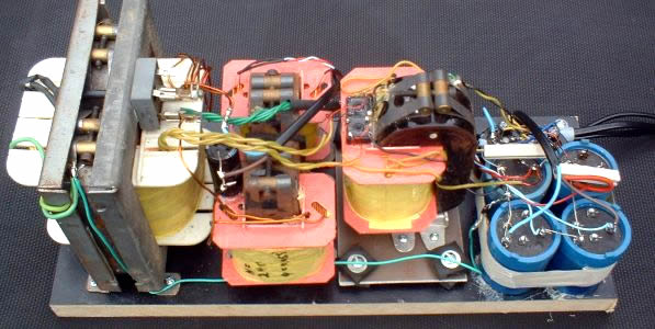
The above pic is a prototype choke input power supply for a 100W per channel ultra-linear valve amp, similar to the above circuit. B+ 560V and 12.6V heaters. C cores are used for the power transformer and chokes.