

We will begin with an overview of a class AB push-pull valve amp, then divide the amp into separate sections. This page will deal with the first section described as the pre-amp, inverter and driver.
Push-pull A valve amp with 2 output valves per channel is described as push-pull. Push-pull is riding a push bike with both pedals. The push bike pedals are 180 deg to achieve a smooth delivery of power and greatest power when necessary. Class A push-pull refers to both output valves amplifying the whole audio sine wave. Our push bike rider pushes down on one pedal with his right leg while pulling up the opposite pedal with his left leg and then visa-versa. Class B is each output valve (in turn) driving one half of the sine wave, with no overlap in-between. No audio amplifier is configured in class B. Both output valves are arranged (biased) so that they begin in class A push-pull, by amplifying the whole sine wave to approx 5 to 20W, and then gradually each output valve will drive more of its half of the sine wave to achieve maximum power. Described as class A push-pull to class AB. This gradual transition from class A push-pull to class AB is transparent.
The amplifier is described in 4 sections.
- A pre-amp valve increases the incoming signal to a higher level.
- An inverter creates a mirror of the signal, in opposite phase 180deg.
- The driver valve increases the 180deg signals to a higher level to drive the output valves.
- The output valves further amplify the 180 deg signals, adding current. The output transformer steps down the high voltage from the output valves to a lower voltage to drive the speaker.
1. The first 1/2 of the 12AX7 amplifies the 100mV RMS input signal to approx 5V RMS.
2. The second 1/2 of the 12AX7 acts an inverter, two 5V RMS signals are created at 180 deg.
3. The 12AU7 driver increases the 5V to approx 50V RMS to drive the KT88 output valves
4. Each KT88 output valve delivers approx 300V x 2 = 600V RMS across the output transformer.
5. The output transformer steps down the 600V RMS (approx 22:1) to approx 28V RMS to drive the 8Ω speaker, 100W approx. The Power supply voltage in valve amps is described as B+
Each of the 4 sections will be described, showing alternative variations used in different valve amplifiers and why the Williamson approach is the most effective method to enable valve amps to achieve the best performance. The Power supply voltage in valve amps is described as B+
Coupling capacitors. The pre-amp, inverter and driver are inter-connected with coupling capacitors. These capacitors block DC from each preceding stage and only let the AC audio signal pass. Any DC leakage through the coupling capacitors (no matter how small) will get to the grid of the following valve disrupting its operation. The majority of service problems with early valve amps was leaking capacitors. Modern capacitors used within voltage rating parameters rarely have leaking problems.
When a large signal spike is created by unplugging or plugging in signal leads or when a pre-amp valve is driven hard into distortion (guitar amps), a large non-symmetrical square wave may cause a temporary DC voltage to appear across a coupling capacitor to the grid of the following valve. This short DC pulse will cause the following valve to be shut off or go into full conduction for approx 1mS to 1 second until the following grid resistor discharges the coupling capicator.
Direct coupled. A few amplifier designs did not use coupling capacitors between each of the stages. The stages were/are directly coupled (not described in this text). The purpose of directly coupled circuits was to remove phase shift between the stages. Directly coupled circuits relied on the valves being in perfect order and any deviation or fault, no matter how small, would be transferred through the stages. Directly coupled valve amps were/are nightmares to calibrate and service.
Pre-amp
Anode load. The pre-amp circuit in the right pic is described as an 'anode load'. The input signal comes in through a .047uF coupling capacitor. The coupling capacitor blocks DC from the outside world and insures only the AC audio signal gets to the grid of the valve. The 1M grid resistor provides a ground reference for the grid representing minimal load to the incoming signal. A 2k2 grid stopper resistor is placed close the pin of the valve socket. The grid stopper blocks Rf (radio frequencies) and parasitics being amplified by the valve. Many amp manufacturers are unaware of the importance of this grid stopping resistor and do not have it in the circuit. The anode current if fed through a 220k resistor from the 250V DC power supply and the amplified signal appears at the anode. Another .047uF coupling capacitor is at the output and blocks DC allowing the AC audio signal to pass.
Bias approx -1V5
 must be on the grid of a 12AX7 to centre the valve in its linear operating position. Without a -V bias on the grid the valve will conduct maximum current. -V on the grid reduces the current flowing through the valve. This is achieved by the 2k2 cathode resistor in series with the cathode. The current flowing through the cathode resistor will cause +1V5 at the cathode. The grid is referenced to ground by the grid resistor. The cathode is +1V5 in reference to the grid which means that the grid appears to be -1V5 in reference to the cathode.
Cathode bias / negative bias. Placing a resistor in series with the cathode to bias a valve is described as "cathode bias". Power valves KT88s etc require -30V to -90V Bias which is supplied from a separate -V supply through the grid resistor described as "negative bias"
Gain. A 12AX7 is a high gain triode (approx 30:1). The gain can be increased to 60:1 by placing a 100uF cathode bypass capacitor across the cathode resistor. Maximum gain is essential for phono and microphone pre-amps but increasing the gain to maximum also increases the noise (hiss) and distortion. The largest problem is caused by the speaker vibrating the air which in turn vibrates the valve elements, generating mechanical resonances, ringing and rattling, interfering with the music. A 12AX7 can be replaced with a low gain 12AU7 (approx 10:1) reducing noise, but only if there is sufficient signal level from the source. No two valves have exactly the same gain. Valve gain reduces in a random manor over its life. Complex valve circuits with self regulating gain was used in expensive test equipment, but rarely in consumer valve amps.
Input and load impedance
Input impedance. The grid of a valve responds to voltage and requires no current from the signal source (there are exceptions not discussed in this text). The grid represents no load to the incoming signal. The grid is referenced to ground through the grid resistor.
The grid resistor represents the input impedance. Grid resistors of 100k 220k 470k and 1M2 are often seen in circuits.
Load impedance. The output impedance of valves is extremely high and anything connected to the output will cause the output signal to be reduced. Valve circuits use high resistance volume and tone controls to insure the minimum load on the output, 500k is typical. High resistance pots (potentiometers) are inaccurate and interfere with the high-frequency response. Solid state circuits are low impedance and volume and tone control pots are approx 10k. Low resistance pots are more accurate and do not interfere with the high-frequency response.
sound-au.com / pots
Cathode follower. 1/2 of a 12AX7 or a 12AU7 can be used as a cathode follower. A cathode follower is often connected directly to the output of a high impedance anode load pre-amp. The cathode follows the signal on the grid without amplifying it.
The signal at the cathode has extra current enabling it to drive a lower impedance load without the output level being reduced, or reduced by a lesser amount. The output of a cathode follower can then be connected to the volume and tone controls or any other circuit that requires to be driven with a lower impedance.
When using a valve as a cathode follower the voltage rating between the cathode and the heater filament is often exceeded. Exceeding voltage ratings within valve elements rarely causes a valve to fail. Unfortunately many valve amp manufacturers have taken advantage of the forgiving nature of valves causing many sloppy design practices to evolve.
Inverters
Two perfect balanced 180deg signals are required for class AB push pull amplifiers. There are many variations of inverter circuits and the split load inverter is possibly the most accurate.
Split load inverter is a combination of an anode load and a cathode follower and represents virtually no load to the preceding pre-amp valve. The two 180deg signals are not increased in size. A balance trim resistor of 1M in parallel with the 47k cathode resistor is sometimes required adjust to the outputs so they are exactly the same level.
The split load inverter remains stable regardless of the condition or age of the valve. 15W per channel amplifiers that use small 6BQ5 output valves can be driven directly by the split load inverter. A following driver valve is required to increase the inverted signals to a higher level to drive KT88s to achieve 100W.
Cathode coupled inverters of which there are many variations are used to drive output valves directly. This is the most commonly used inverter. Almost all valve guitar amplifiers use this inverter. The primary advantage is that it amplifies and creates two balanced 180deg signals within the one function. This enables the minimum number of valves to make an amplifier, thereby economically rational for mass production when needing to control costs.
The input signal goes to the grid of the first triode of a 12AX7. The grid of the second triode is AC referenced to ground through a 0.1uF capacitor. The cathode of the first triode follows the input signal because the 2 cathodes are connected together the second triode is forced to amplify the audio signal in the opposite phase.
But cathode coupled inverters can not create 2 exact 180deg balanced signals. Depending on the differences between each half of the 12AX7 the outcome is inconsistent. Also the two 180deg signals shift further apart in level as the valves age.
12AU7 Driver
To drive a pair of KT88's to 100W, the balanced signals from the split load inverter need to be increased to a higher level. A 12AU7 driver valve amplifies each of the balanced signals to 50V RMS. That means there is 100V RMS between the 2 balanced signals to achieve driving the KT88's to full power. At lower levels where the amplifier is driven to 50W the driver valve contributes no distortion. The driver valve begins to reach maximum level slightly before the KT88's reach full power. Therefore slightly extra distortion is added by the driver valve as the KT88's reach full power. This is not considered a problem because a 100W amplifier is not intended to be driven at 100W. Also the slightly added distortion contributed by the driver valve reaching its limitation at 50 to 60V RMS is inaudible.
The 2 triodes inside the tube are rarely identical. It is essential to select a 12AU7 that has as close to identical twin triodes as possible. Each triode within a 12AU7 should have the same voltage at the anode and should have the same gain. Possibly only 1 in every 5 12AU7s will have close matching triodes with similar gains. Therefore it is essential to have approx 10 12AU7s from which to select the best 2 to make a stereo amp.
Driver balance. The 12AU7 driver circuit in the right pic has been re-drawn and rotated to show the 10k balance adjustment trim pot. The 12AU7 driver valves should be selected to insure both triodes in each 12AU7 are identical by having the same quiescent DC voltage at the anodes, 180V DC approx. The 10k adjustment trim is adjusted so exactly the same signal level is achieved from each anode.
The KT88's should be selected as identical pairs. Approx 12 KT88's are required to select 2 identical pairs for each channel. However, very few people have this number of spare KT88's to select from, therefore very few amps will have identically matched KT88's.
The 10k trim pot must be used to adjust the drive voltage to insure that both KT88's are performing identically even if the inverted audio signals from the driver valve are now at different levels. Whenever a 12AU7 driver valve or KT88 output valves are replaced this balancing procedure should always be repeated.
AC boot-strapped driver. This drive circuit was created by Rod Elliott (sound.whsites.net). A zero distortion driver circuit can be constructed by adding an extra 1/2 of a 12AU7 as a cathode follower. The audio AC signal from the anode of the first 1/2 of the 12AU7 is directly connected to the grid of a cathode follower which is the second 1/2 of the 12AU7. The cathode follower can drive a lower impedance with more current added to easily drive the KT88's to full power. The output of the cathode follower is also fed back through another 0.47uF capacitor to the junction of 2 resistors in series (150k 47k) of the previous anode load pre-amp. The same audio AC signal appears on both ends of the 47k resistor, therefore there is no audio AC voltage 'difference' across the 47k resistor. The only voltage difference across the 47k resistor is the DC bias current. The current through the first 12AU7 always remains the same and no non-linearity (distortion) of the AC amplified audio signal can be created. This circuit technique is described as a an AC boot-strapped constant current source. This circuit will remain free of distortion to the very limit of its driving capacity which is greater than what is required to drive the KT88's to full power.
The 2 triodes inside any twin triode valve are rarely identical. It is essential to select 2 12AU7s that have as close to identical twin triodes as possible. Each triode within a 12AU7 should have the same voltage at the anode and should have the same gain. Approx 1 in 5 12AU7s will have close matching triodes with similar gains.
Pre-amp, inverter, driver
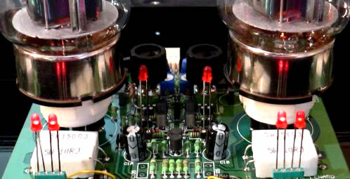
The completed pre-amp, inverter and driver circuit in the pic below is constructed as a single entity which makes seeing the separate sections difficult to recognise particularly by those who are not skilled in understanding electronic circuits. There are many subtle various in how these circuits are constructed, however the end result is to achieve driving the output valves to pull power.
The largest problem with valve amps is the inconsistency of gains between the 2 triodes in the 12AX7 and 12AU7s, making it almost impossible for any 2 valve amps to perform identically. Having to adjust the balance between left-right channels each time the amp is turned on, then having to re-adjust the balance while listening to the music was part of the experience of owning a valve amp. Many amps of the same model could vary considerably. When purchasing a new valve amp, discerning music lovers would select a new amp from 3 or more of the same model. Also the inconsistencies between valve amps made it difficult for active systems greater than 2-way, to evolve.
Solid-state driver
The heart of a valve amplifier is the output valves and output transformer. Only the output valves and output transformer contribute to the unique sound character that makes it distinctly different from a solid-state amp. The pre-amp, inverter and driver only increase the size of the signal to drive the output valves. The pre-amp valves provide no uniqueness to the sound. During the era of valve amps (pre 1970) speakers were approx 6dB to 10dB more efficient than the majority of speakers today. The hum, hiss and microphonics (ringing and rattling) of pre-amp valves was clearly audible.
The above pic shows the pre-amp valves substituted with two discretely made high voltage op-amps. Op-amps are described in the amplifiers chapter. The advantage of solid-state op-amps is zero noise, zero distortion and identical gain with precision accuracy. An op-amp has 2 inputs +non-inverting input and -inverting input. The audio signal first passes through a coupling capacitor to block any DC from the outside world. The 4k7 resistor in series with the +input limits noise and Rf being amplified by the op-amp. The op-amp gain is controlled by R1/R2. The output of the first op-amp also goes through a 100k resistor to the -input of the inverting op-amp, which has unity gain. Two 180deg signals are sent to the output valves.
Major advancements in industrial and chemical engineering took place from the mid 1960's onwards, driven by demands of military and aerospace. Electronic components today (resistors capacitors etc) are infinitely superior to the components that were available pre 1960. Russian scientists continued with advancing valve technology beyond what the West had previously achieved. Many advancements such as the AC boot-strapped driver and solid-state drivers etc for improving the performance of high powered valve amps were starting to be recognised during the mid 1960's, but were not implemented because solid-state technology took over. Many valve amps made today are replications of pre 1950 technology when valve amp designs and performance was restricted by limited knowledge and component technology. By using modern components and innovative solid-state driver circuitry we are now able to make a valve amplifier that is considerably superior to the valve amps of the past. But first we have see through the infantile audiophile beliefs and marketing nonsense that describe pre 1950 valve amp technology as being magical.