

The output stage consists of three sections.
- The negative bias circuit adjusts the output valves to their linear operating position.
- The KT88 output valves and current monitoring circuit.
- The output transformer.
1. A negative bias adjustment circuit applies approx -85V to the grids of the KT88's.
2. The KT88's are calibrated to 50mA each quiescent current, and checked that they are matched.
3. The KT88's are tested at full power.
4. Each KT88's delivers approx 300V x 2 = 600V RMS across the output transformer.
5. The output transformer steps down the 600V RMS (approx 22:1) to approx 28V RMS to drive the 8Ω speaker to full power, approx 100W.
The -V bias adjustment, KT88 quiescent current calibration and the output transformer will be described, showing alternative variations used in different valve amplifiers and why the Williamson design was chosen as the most effective method to achieve the best possible performance.
Quiescent current
Cathode bias - negative bias
Cathode biasis described as class A. Using 2 output valves is described as push-pull. 2 output valves that are cathode biased is described as class A push-pull.
Most output valves in hifi valve amps (40W and less) are cathode biased in the same way that pre-amp valves are biased. The grids are referenced to ground (chassis) by a 220k resistor. Cathode bias is mostly used in low cost valve amps that function from a 300V to 400V B+ supply.
A large 10W 470R resistor or similar value resistor is placed in series with each cathode. The value of the cathode resistor depends on the type of output valves and the B+ supply voltage, 470R is selected for this explanation. Without a -bias voltage on the grids the output valves attempt to go into full conduction, maximum current. The current through the valve also flows through the 470R bias resistor causing a +voltage to appear across the cathode resistor.
The +voltage across the 470R cathode resistor will increase until it reaches approx +30 to +35V and the current will stabilise and self regulate. +35V across 470R is 74mA. The 470R resistor can be changed to a different value to select the quiescent current required. The +35V at the cathode is in reference to the grid, which means that the grid is -35V in reference to the cathode. The advantage of cathode bias is that it is self regulating. Miss-matched or old valves make little difference to the amps performance. Many valve amp manufacturers use cathode bias because it is cheap, any valves will work, no calibration required.
Cathode biased amps are less powerful than negative biased amps operating form the same B+ supply voltage. As the current through the valve increases with the signal level, so does the cathode voltage, thereby modulating the quiescent current of the valve. Excessive inter-modulation is generated as the power increases and the transient response is poor.
Output valves in cathode biased amps operate at maximum allowable temperature (quiescent anode dissipation). An EL34 (6CA7) is rated at 25W. A 6550 is rated at 30W. A KT88 is rated at 35W. 35V across a 470R resistor is 74mA. 74mA is the current flowing between anode and cathode from a B+ supply of 380V. 74mA x 380V = 28W. Therefore, each output valve is dissipating 28W of heat regardless of whether it is amplifying music or not. This anode to cathode heat dissipation is in addition to the heat generated by the filament. This example amp can only deliver approx 30W to drive the speaker. Cathode biased power valves cause increased inter-modulation distortion and have a poor transient response.
 Negative bias is the correct method to bias power valves. A separate -voltage supply provides an adjustable -bias voltage to the grids of the output valves. The -bias voltage required to centre the valves in their linear operating position will depend on the B+ supply voltage. Also, the -bias voltage will be different for ultra-linear and tetrode configuration.
From a B+ 400V supply a pair of KT88's will give approx 45W, and a bias of approx -40V is required on the grids to centre the valves in their linear operating position. From a B+ 560V supply a pair of KT88's in ultra-linear configuration will give 100W and a bias of approx -80V is required on the grids to centre the valves in their linear operating position. The right pic shows the adjustable -bias method.
A 2k2 resistor is placed close to the grid (right pic) to help stop parasitic Rf oscillation. An adjustable -bias voltage (from a potentiometer) through a 100k resistor is connected to the KT88 grid. This means that the driver valve is supplying the audio signal into a 100k load. The -bias voltage must be stable, free of noise and power supply ripple.
Without a -bias voltage on the grids the power valves will conduct maximum current and damage the valves. When the amp is switched on the -bias voltage should appear immediately on the grid. When the amp is turned off, the -bias voltage should remain after the other supply voltages have collapsed to zero. When turning a valve amp off avoid turning it on again until it has cooled down. The -bias voltage should appear at the grid, prior to the B+ 560V supply voltage.
The below pic is the same circuit of the output stage rotated horizontally to enable each of the points discussed to be easily seen.
Bias current. The purpose of the 10R resistors in series with the cathodes is to monitor the current flowing through the power valves. The 10R resistor has no effect on the valves operation. Meters should be permanently connected across the 10R resistors so the current through the resistor (and valves) can be monitored and adjusted when necessary.
Unfortunately bias current monitoring meters, or a dual LED monitoring circuit to achieve the same function, is rarely seen in valve amplifiers. It is irresponsible for valve amp manufacturers not to provide accessible bias calibration and monitoring on every valve amp.
Flash-over The 10R bias monitoring resistors should be wire wound (5W). Low value wire wound resistors are often +- 20%. Therefore, the resistors should be individually measured and matched. A faulty valve can flash-over between the elements. The physics of flash-over is similar to lightening. At the moment of flash-over a negative resistance is created that magnifies the current. A normal resistor can be vaporised, depositing a carbon film throughout the amp. A wire wound resistor will survive or act as a fuse.
50mA. The -bias voltage is adjusted to achieve 500mV (0.5V) across the 10R resistor which is 50mA flowing through the valve. The -bias voltage for each valve must be independently adjusted so the same current is flowing through each valve. Increasing the bias current shifts how far the valve will remain in class A before gradually transferring to class AB as the audio signal increases. It is inexcusable for bias monitoring with -bias adjustment not to be available in every valve amp.
KT88's from a B+ 560V DC supply should not be biased less than 40mA and no higher than 60mA. Adjusting the bias also sets the quiescent dissipation (temperature) of the valve.
- 560V x 40mA = 22.4W
- 560V x 50mA = 28W
- 560V x 60mA = 33.6W
The maximum quiescent dissipation for a KT88 is 35W. Increasing the KT88 above 35W will cause the anode plate to become molten red and the life of the tube will be reduced. Reducing the quiescent dissipation below 20W will shift the valve to its non linear operating position.
KT88's from a B+ 400V DC supply should not be biased less than 50mA and no higher than 75mA.
- 400V x 50mA = 20W
- 400V x 60mA = 24W
- 400V x 75mA = 30W
The anode heat dissipation is in addition to the heater filament. A quiescent anode dissipation 25W plus the filament heat of 10W, the total heat generated by a KT88 is approx 35W to 40W.
No bias adjustment. Some valve hifi amps and many valve guitar amps do not have independent adjustment for the -bias voltage to each grid of the output valves. Many guitar amps only have a single adjustment for both valves. In some amps the -bias voltage is fixed with no ability to adjust the -bias voltage. Many celebrity brand valve amp manufacturers copy each other (including mistakes) and are often found to be ignorant of understanding the need to independently adjust the bias current to centre the power valves in their linear operating position. Because output valves can vary greatly, many valve amps can have one power valve glowing molten red and the other so cold it can easily be touched.
Maximum B+ supply voltage
Most octal based output valves will function reliably from a B+ 400V supply and deliver 30 to 50W from a pair in push-pull. Valve data sheets are readily available on the internet. The higher the B+ voltage the greater the power, but what is the maximum ?
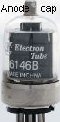
Many power transmitting tubes (6146) operate at voltages well above 600V and have been used in audio amps. The anode pin is on the top of power transmitting tubes (right pic) to insure high voltage flash-over cannot occur. Many audio power valves evolved from transmitting tubes and therefore the anode is often capable of much higher voltages than the spacing between the pins of a conventional octal base will allow.
The anodes of EL34 (6CA7) and KT88 can function from a B+ 800V supply but with a high B+ supply voltage above +600V, flash-overs can and do occur. The upper recommended limit is +560V.
Carbon footprint
Power efficiency. At 10W each KT88 is conducting 160mA. A pair of KT88s is conducting 320mA total. 320mA x 560V = 180W. 180W is consumed from the B+ for an audio output of 100W to the speaker. Plus, the filament consumes 10W to heat each KT88. 20W + 180W = 200W (50% efficient).
The conversion of 120V 240V AC mains to B+560V is 70% efficient. 200W x 1.4 = 280W. 280W is consumed from the AC mains to deliver 100W to the speaker. A 100W valve amp at full power is approx 35% efficient, not 50% efficient.
At sensible room listening level a stereo 100W per channel valve amp has 4 x KT88's at 50mA quiescent current each = 200mA. 200mA x B+560V = 112W. Calculating for 70% efficiency conversion from the mains = 112 Watts x 1.4 = 156W, plus 40W for the filaments to heat the valves = 196W. Add a couple of watts for music = 200W. Grand total 2% efficient. Therefore, a valve amp has a high carbon footprint.
Triode, tetrode and ultra-linear.
Triode operation. If the screen is connected to the anode then the valve behaves as a triode. In triode operation, power output is reduced to being almost useless. Some audiophiles claim that the laws of physics are transcended and magical transformations occur when the screen and anode of a KT88 or EL34 etc are connected together and the valve is forced to function as a triode.
Tetrode configuration is the most efficient method to obtain maximum power at low cost with minimum mass. Most cheap hifi valve amps and almost all guitar amps are in tetrode configeration.
Ultra-Linear gives the same power as tetrode configuration with lower distortion figures than triode operation. Ultra-linear is slightly more complex, higher cost and higher mass.
Tetrode configuration
Tetrode circuit configuration, is where the screens of the power valves are connected to a separate stable B+ supply that has extra filtering, regardless if the output valves are tetrodes, beam power tetrodes or pentodes. The purpose of the screen is to increases the efficiency and gain of the valve, enabling the valve to achieve approx x3 more power than as a triode.
Approx 50% of hifi valve amps and almost all valve guitar amps are configured in tetrode operation. Removing the B+ voltage from the screen shuts off the valve, quiescent current is zero. Many guitar amps have a standby switch that simply disconnects the B+ voltage from the screens.
Tetrode configuration is the most efficient method to obtain maximum power from output valves. A good pair of KT88's can easily achieve 100W from a B+ 560V supply. It is recommended that the screens have a separate supply voltage not in excess of 400V. A bias of -40V is is required on the grid to set the correct quiescent current of 50mA through the output valves. A drive signal of approx 30V RMS will easily drive a pair of KT88's to full power.
In tetrode configuration the screens of almost all output valves are not designed to be supplied with a B+ above 400V. Only the KT88 KT90 and 6550 can withstand a B+ on the screens above +400V, providing the valves are not driven to full power.
400V Screen. The screen is not intended to conduct current. With a screen voltage above 400V the valve must not be driven at full power for more than a few seconds. In the quiescent position (zero signal) no current flows through the screen. As the signal is increased a small current flows through the screen. Just prior to the valve reaching full power (with a screen voltage above +400V) screen current rapidly increases which can harm or destroy the valve. The majority of valve guitar amps have a screen voltage above 400V. The valves are easily destroyed when constantly driven into full power distortion.
A B+ voltage less than 380V on the screen will limit the valves achieving full specified power. A B+ of 380V is the minimum screen voltage that will enable EL34 (6CA7) and KT88 to achieve maximum specified power with minimum current through the screen. A screen voltage above 400V will not enable the valves to give greater power than specified. +400V is the maximum V that should ever be allowed on the screen. Above +400V the screen will conduct excessive current and damage the valve when driven at high power.
Screen resistor. A resistor should always be placed in series with the screen as close to the valve pin as possible. This helps limit the excessive current into the screen at full power and also restricts parasitic Rf oscillation. In guitar amps which are constantly driven at full power, the screen resistor should be 5W rating approx 470R to 1k.
Guitar amps. The majority of guitar valve amps have a B+ 500V which also supplies the screens. When valve guitar amps were originally designed it was inconceivable that rock musos would drive them into hard distortion most of the time, reducing valve life to a fraction. Because these problems still exist today, it demonstrates that guitar amp designers appear to be mostly unaware of the physics of valve behaviour when the amp is constantly driven into hard distortion.
Regulated screen. The supply voltage on the screen effects the gain of the valve. It is essential that the screen voltage be stable (regulated) and should not change (reduce) when the amp is driven to full power. Tetrode configured hifi amps are rarely designed with a circuit to regulate the screen voltage. This is considered unnecessary because hifi amps are rarely driven at full power. All that is provided is extra filtering to insure 100Hz / 120Hz power supply ripple does not get to the screens.
The power transformer in valve guitar amps is made as low weight as possible. The regulation of a power transformer is dependant on it's mass. Most guitar amps have poor (soggy) B+ supply regulation. When the amp is driven to full power the B+ supply will often drop by 50V to 60V.
At full power, the over voltaged screen draws excessive current and the tube is almost always partially damaged. As the B+ supply voltage drops when the amp is driven at full power, so does the screen voltage, partially limiting the excessive screen current. But, as the B+ to the screen drops so does the gain of the valve, shifting the valve outside of its linear operating position toward class B and excessive distortion is created, particularly inter-modulation distortion.
False statements are made to justify that this dramatic increase in distortion as being desirable and what musicians want, claiming this makes valve amps magical and warm. When musicians are given the opportunity to play through a valve amp that has a stable power supply and regulated screen voltage they immediately recognise the superior performance and prefer it. Unfortunately very few musicians get the chance to hear this comparison.
Ultra-linear
In ultra-linear configuration the screens are connected to tap positions on the primary of the output transformer (40% to 50%). The screens are partially connected to the anodes resulting in the valves behaving as triodes, but with the full power capacity of tetrode configuration. The screens are modulated with 50% of the audio signal that appears at the anodes. The result is win win. The fidelity and reduced distortion figures are superior to triode operation, with higher power equal to tetrode configuration.
The Screen acts as a second grid modulating the gain of the valve in opposite phase to the anode. This return path acts as an automatic negative feedback that removes most if not all residual distortion created by the output valves and output transformer. This local feedback from the 50% primary taps to the screen results in the speaker connected to the secondary being included in the UL feedback structure.
The output impedance from the secondary winding tends to reflect the speaker impedance. A remarkable result is that this reflected impedance tends to naturally maintain constant power to the speaker over the frequency spectrum, providing the ideal damping that enables the speaker to give the most pleasing musical performance.
Ultra-linear amps are higher cost to make. The output transformer is more complex, the output stage has low gain and the output valves require x 2 greater audio signal 50V RMS approx to drive KT88s to 100W. A -bias voltage of approx -80V is required to centre the valves in their linear operating position (quiescent current 50mA). A tetrode amp with 400V screens requires approx -40V bias for the same quiescent current.
EL34 (6CA7) and most smaller power octal based valves can only be used within the screen voltage parameters, therefore a B+ 400V supply for ultra-linear application is the maximum allowable, approx 30W to 40W.
KT88's were specially designed for ultra-linear operation to give 100W from a B+ 560V supply. Many 6550's and KT88's can be interchanged but some 6550's will not function reliably from a B+ 560V supply. Unfortunately some KT88's are relabelled valves similar to the 6550. Anything to do with audiophile land is open to scams. The EH KT90 is now superior to the KT88 and is possibly the most reliable valve to use today for the 100W ultra-linear amp.
The power supply must be absolutely stable (greater mass) and free of power supply ripple and noise. Any modulation on the power supply is directly transferred to the screens resulting in the gain of the output valves being modulated causing inter-modulation distortion. Providing all quality conditions are met, the Williamson ultra-linear is the best performing design of a valve amp.
Negative feedback (local - external)
There are at two different types of negative feedback in valve amps. Local negative feedback is applied around a pre-amp stage. Local negative feedback forces a pre-amp stage to be linear, reducing its internal distortion. A typical example is is a high gain microphone pre-amp which requires an exact specified gain. Another example is a high gain phono pre-amp which includes accurate RIAA EQ management.
www.wikipedia.org / RIAA equalizationExternal negative feedback is the process of feeding back a small amount of signal from the speaker output to the cathode of the pre-amp valve (in opposite phase) to reduce the overall gain of an amplifier. External negative feedback has a limited effect on reducing distortion because the output cannot be exactly 180 deg out of phase with the input at all frequencies. 6dB to 12dB feedback is the maximum that can be achieved before most valve amps are caused to oscillate.
Almost all valve amplifiers have external negative feedback but external negative feedback is not required to enable a valve amp to function. If the external negative feedback is removed the amp will appear to sound more responsive with approx 6dB to 12dB more gain. The immediate experience is sound quality has improved.
What is the purpose of external negative feedback in valve amps?
The primary purpose of negative feedback in valve amps is to quieten the amplifier. Valve amps are naturally noisy and in the past (before solid-state) there was nothing to compare them with, therefore a small amount of hum and hiss was considered normal. Instead of stating "negative feedback reduces the noise of the amp", the emphasis was to state the benefit as "negative feedback reduces distortion".
Thermionic hiss and mechanical rattling of the valve internal elements is clearly audible. Tapping a valve with a finger reveals this. The valve filaments in the majority of valve amps are fed with 6.3V AC from the mains transformer. Hum leakage from the AC current flowing through the filaments is imposed on the cathodes. EI power transformers induce eddy currents into the chassis which is heard as a residual background hum. Valve amp circuits do not have common mode rejection, therefore any ripple from the power supply, no matter how small, introduces a small audio hum which also causes amplitude modulation of the audio signal.
Because the majority of domestic valve amps were 15W per channel or less, speakers were made as efficient as possible (approx 6 to 10dB more efficient than the majority of speakers today). The excessive noise generated by valve amps is clearly audible with high efficiency speakers. Valve amp noise is less noticeable with most modern less efficient speakers.
Distortion reduction. Negative feedback reduces the hum and hiss of a hifi valve amp, but has little to zero effect on reducing audible distortion. Many so called valve amp experts will have a hostile reaction to this statement. The theory and education behind electronics technology of the past concentrated on telecommunications and not hifi amps. Valve telecommunication repeater amplifiers are very different, where negative feedback had a large effect in reducing distortion. This is where much of the confusion about negative feedback in hifi valve amps came from.
www.wikipedia.org / Negative feedback
www.wikipedia.org / Harold Black
The most significant effect of negative feedback is reducing the output impedance, providing more damping to the speaker. Many high quality valve amps made during the 60's allowed the negative feedback to be adjusted to tune the damping of the speaker.
Matched valves
When purchasing matched valves do not trust that they are matched. The only advantage in purchasing matched valves is that they may have been checked that they work, and if one is faulty the distributor may replace it without question. The only way to insure valves are identically matched is to do it yourself or know someone you trust to do it for you.
Output valves in a push-pull amplifiers should be close to identical. This is similar to vehicle engines having balanced pistons. Unfortunately no two output valves are identical. However, it is essential to select 2 KT88's that are identical. 20 output valves are sometimes required to select 2 pair that are close to identical.
1. Select 2 valves that conduct the same bias current with the same -bias voltage on the grid.
2. With a 400Hz sine wave, drive the valves to 100mA (3/4 power). Check both valves are the same.
- GM - represents the gain of a valve.
- Plate resistance - represents the maximum current when driven.
A pair of power valves may have similar quiescent current with the same -bias voltage, but will have different gains when driven with a audio signal. The valves should be identical with the same -bias voltage and also have identical gains when driven with a signal. At full power the valves should conduct identical current approx 150mA each. The parameters of GM and plate resistance of each pair of valves must be equal. &Approx 20 valves are required to select matched pairs.
No bias adjustment. Some valve hifi amps and many valve guitar amps do not have independent adjustment for the -bias voltage to each grid of the output valves. Many guitar amps only have a single adjustment for both valves. In some amps the -bias voltage is fixed with no ability to adjust the -bias voltage. Many celebrity brand valve amp manufacturers copy each other (including mistakes) and are often found to be ignorant of understanding the need to independently adjust the bias current to centre the power valves in their linear operating position. Because output valves can vary greatly, many valve amps can have one power valve glowing molten red and the other so cold it can easily be touched.
Balanced driver. The driver valve should be selected to insure both 1/2 of the 12AU7 is identical by having the same quiescent DC voltage at the anodes, 180V DC approx. Some driver circuits have a 10k trim adjustment in series with the 41k anode resistors to balance the drive signal. This adjustment can also be used to adjust the drive signal to compensate for miss-matched output valves. Whenever the driver or output valves are replaced this balancing procedure should be repeated.
Fingerprints. Do NOT put fingerprints on output valves. Clean the glass if you touch it.
 Coupling capacitors. The coupling capacitor between the 12AU7 driver and the KT88 should be the highest quality 600V rating. Absolutely no DC leakage must occur through this capacitor. Any DC leakage no matter how small will interfere with the -bias voltage on the grid of the KT88. If this capacitor failed (short circuit) the KT88 will go into full conduction and be partially destroyed. Also, be wary of audiophile marketing scams selling relabelled capacitors glossy black with gold lettering as having a magical sound.