

This 7 page chapter on valve amps is centred on understanding the operation of the Williamson Ultra Linear 100W valve amp. Valve technology is now redundant and there is no point discussing valve amp designs that fall short of achieving the highest performance for replicating music.
Rod Elliott (sound.whsites.net) has also written chapters on valve technology. We have collaborated on what we are best able to describe with minimum overlap. It is essential to read the valve chapters on both sites to obtain a pragmatic understanding of valve amp technology.
sound-au.com / valves
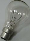
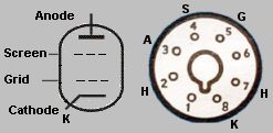
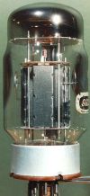
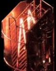 A valve is an extension of the light bulb - inside the valve is a vacuum. The glowing hot filament in the centre of the valve is the 'cathode'. The letter K represents cathode. The metal plates on the outside of the cathode is the 'anode'. The thin helical wire between the cathode and anode is the 'grid'. The right pic shows the inside of a triode (view these links).
userweb.117.ne.jp / A-08S-205D-amp-e
www.6moons.com/audioreviews/yamamoto/a08_2.html
When a +voltage is placed on the anode and a -voltage is placed on the hot cathode, a current can flow between them, but not the other way around. This function is described as a 'rectifier'. The solid state diode uses the same symbols as the valve (anode A, cathode K).
The red arrow in the right pic symbolises that current is conducting between anode and cathode. The direction of the arrow does not refer to the direction of current flow, but only that conduction is happening. Early academic text of valve technology sometimes refers to current flowing from cathode to anode. Later academic text of solid-state technology sometimes states that current flows from anode to cathode, confusing to say the least. From quantum mechanics we know that electro-magnetic energy functions at the speed of light (4th dimension) where time and direction do not exist. Therefore, this text does not refer to current flowing in a direction.
Heater filament. In the earliest valves the heater filament and cathode K was the same element, described as a directly heated cathode. Approx 1940 onwards (except rectifier valves) in the majority of valves the heater filament and cathode are separate elements. The cathode is indirectly heated by the filament. The majority of valve filaments is 6.3V. Early vehicle batteries were 6.3V.
The temperature of a filament can be as high as 2,000 deg C. In small pre-amp valves the filament current is 6.3V x 300mA = 2W approx. The filament current in large power output valves can be 6.3V x 1.5A = 10W approx. Because the 6.3V heater filament is common to all valves, the heater filament does not need to be drawn in the circuit.
Triode. A fine helix (spiral) wire is placed close to the cathode. A valve with a single grid between anode and cathode is a triode. Without a voltage on the grid (0V) the current between anode and cathode will be maximum (saturation). -V on the grid will reduce the current between anode and cathode. A small audio signal on the grid can modulate the current between anode and cathode. When a valve is applied in a circuit the modulated audio current between anode and cathode will appear as a large amplified signal, as a perfect replica of the input, rotated 180deg in phase.
Thousands of variations of valves evolved since the 1920's. The only valves discussed in this chapter are those required for the Williamson 100W Ultra Linear amplifier. These valves were readily available from the mid 1950's onward and became the most popular valves used in the majority of high-fidelity valve amps until solid-state technology took over in the late 1960's. Occult magical audiophile valves and single ended class A amps of the 1930's are not discussed in this text.
Valves for audio amplifiers are categorised into three primary groups.
A Small (noval base) pre-amp twin triode 12AX7 and 12AU7. 12AT7 12AY7 similar but less used.
B Small (noval base) power tubes for 10 to 15W amps. EL84 6BQ5
C Large (octal base) power tubes for 30 to 100W amps. EL34 6CA7 6550 KT88 KT90
12AX7 (ECC83) and 12AU7 (ECC82) are twin triodes. ECC83/82 are the European numbers for these valves. There are 2 separate triodes in each valve. They are the most commonly used small valves for pre-amplifiers and signal processing. They only conduct a small amount current between anode and cathode. Small pre-amp valves function between +100V to +300V DC and conduct 0.5mA to 3mA (average) and can be touched without scorching your fingers.
The 12AX7 is for high signal gain (approx 40), whereas a 12AU7 is capable of driving a lower impedance and will be of lower gain (approx 10). The letter A is placed at the end as 12AX7-A and 12AU7-A to represent high quality and low noise. Many variations of these valves were produced by valve manufacturers from the 1940's to the 1960's, that have similar numbering 12AY7 12AT7 etc. Most of the twin triodes have a standard noval (9 pin) base with the same pin configuration. The heater filaments can be paralleled for 6.3V or wired in series for 12.6V. 6.3V and 12.6V was the standard for vehicle batteries. Heater filaments are normally connected to AC from the mains transformer. DC for the heater filaments was and is used to eliminate hum leakage into the cathode when used for high-gain phono pre-amplifiers and microphone inputs.
Numbering. When solid-state technology took over nearly all valve factories in western countries closed. What evolved was the numbering variations on many valves, including twin triodes, being reduced to represent application rather than technical parameters in the original RCA valve manual - e.g. 12AX7 for high gain and 12AU7 lower impedance, low gain. When purchasing other variations of twin triodes 12AY7 12ATY etc today, to be used for specific application where substitution is not appropriate, it is wise to test if these other valves are still of the original RCA specification or are the same as the presently available 12AX7 and 12AU7 relabelled.
Power valves conduct a large amount current and have extra internal elements to enable them to function at greatest efficiency and lowest distortion. Large power valves function between +300V to +600V DC and conduct 50mA to 150mA (average). The heat generated by the current flowing between anode and cathode is in addition to the heat generated by the heater filament. Large power valves can dissipate 30 to 50W of heat and will readily scorch unwary fingers.
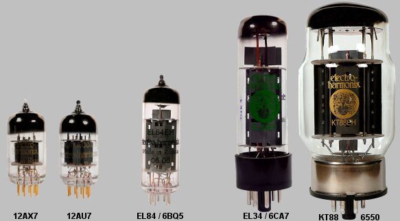
6CA7 EL34 is an octal base output valve described as a power pentode. These large valves were mostly used in independent chassis high-fidelity amplifiers. 2 x 6CA7 class AB push-pull was used by the majority of 35W per channel valve amplifiers with a 375V DC power supply. The 6CA7 / EL34 has high gain requiring minimum pre-amp circuitry to drive them to full power.
 Some European amp manufacturers used 800V DC supply which enabled a pair of EL34s to achieve 100W. During the 1960's EL34s were very cheap $1.50 each in packs of 100 and readily available, therefore 6CA7 was the preferred power valve for many amplifier manufacturers to use.
6V6 6L6 7591 KT66 were and are lower power octal based power valves that pre-date the 6CA7, KT88 and 6550.
Screen grid. Another fine helix (spiral) wire is added and placed between the grid and anode. A power valve with an added screen grid next to the anode can be described as a tetrode or pentode. The screen is always kept at a high +V. A high +V on the screen increases the current efficiency between anode and cathode and magnifies the gain of the valve. A very small change in the -V on the grid will now cause a larger current change between anode and cathode. 0V on the screen will cause the current between anode and cathode to be zero (cut-off). Switching off the supply voltage to the screens is used as a standby method in some guitar amps.
Different power valves have variations of extra elements, but only the anode, grid, screen and cathode are externally accessible. Other internal elements (suppressor grids and beam plates) are internal connected and are not externally accessible.
Tetrode and pentode. A triode has 3 elements that are externally accessible (anode, grid, cathode). The tetrode and pentode have 4 elements that are externally accessible (anode, screen. grid, cathode). The extra screens described as suppressor screens and beam plates are internally connected and are not externally accessible. Variations of tetrodes and pentodes evolved as a means of getting around eachother's patents. A KT88 is a beam powered tetrode, whereas a 6CA7 (EL34) is a power pentode. Both valves use the same large octal base arranged in the same pin configuration for anode, screen, grid and cathode, including the 6.3V heater filament. Many patents have lapsed and the numbering on valves today represents marketing application rather than the internal structure of how a valve is made.
Internal differences. A person who constructs valve amps does not need to be concerned with the internal differences of how a triode, tetrode or pentode is designed or constructed. Understanding the internal parameters of valves is academic. Many people who make valve amplifiers have a good understanding of the academic parameters of valves, but many people who make valve amps appear to have a limited and narrow understanding of valve physics when applied in a circuit. This is demonstrated by the bewildering and illogical variations of valve amp designs including basic circuit design mistakes, particularly with power valve biasing.
6BQ5 EL84 (and 6GW8 EL86) is a small noval base power pentode. Many cheap stereo systems used one 6BQ5 per channel (class A) approx 4W. The majority of domestic high-fidelity stereo systems used 2 x 6BQ5s in class AB push-pull, and are capable of 16W. Many stereo systems that used these small power valves were marketed as 30W total.
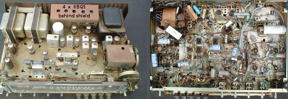
The above pic is a 1960's National SA-52H (30W) FM stereo-tuner integrated hifi amplifier that included a multitude of features. A total of 18 valves, 4 x 12AX7, 3 x 12AU7 and 7 radio tuner valves, plus 4 x 6BQ5 power valves behind a heat protection shield at the rear of the chassis. Class AB push-pull 15W per channel. The transformers were high quality. Hundreds of thousands of variations of these products flooded the world market. hey were hand wired in a birds nest manor using cheap labour. Most of these domestic amps performed well, but were nightmares to service.
KT88 and 6550 are large octal base output valves, described as power tetrodes. KT88 and 6550 are almost identical and can be interchanged in most applications. These were the highest performing octal based tubes available. A pair of KT88s in UL class AB push-pull were the preferred power valves in the more expensive high-fidelity amps, 50 to 60W per channel. A pair of KT88s can achieve 100W from a 560V DC supply. The KT88 is low gain, requiring extra pre-amp circuitry to achieve a large signal voltage to drive a pair of KT88s to full power. During the 1960's, KT88s were approx $10 each and difficult to source in quantity. Today, KT88 and 6550 are readily available from many suppliers and in comparison to today's money value they have decreased in price.
Williamson is the name of the person attributed to rationalising how valve amplifiers could be made to achieve the highest technical performance. His scientific articles appeared in the late 1940's and by the mid 1950's many variations of the Williamson Ultra Linear Class AB AB1 amplifiers became available (15W to 100W). www.wikipedia.org / Williamson amplifier
The following pages of this chapter will describe how a Williamson UL Class AB AB1 amplifier works and how valve amps can be serviced and maintained to give the best performance.
 In 1956 MOV (Marconi Osram Valve) subsidiary of G.E.C, re-modelled the TT21 transmitting tube, naming it KT88. The KT88 was designed for high-power low-distortion domestic and commercial amplifiers to give the best performance from the UL Williamson design. But, the KT88 was approx x10 greater in cost than the majority of output valves that were currently available, thereby restricting their use only to the highest quality and most expensive amplifiers, which very few people could afford. The average output valve in most 15W to 30W amplifiers was less than $1 for amp manufacturers to purchase in quantity. The KT88 was approx $10 for a amp manufacturer to purchase and a pair of KT88s would have equalled half the average weekly wage. By the time that cost is passed on at retail in a finished amplifier using KT88s the price was simply prohibitive for the majority of consumers. If KT88s were available at low cost, every amp manufacturer would have used them.
www.wikipedia.org / KT88
In 1956 MOV (Marconi Osram Valve) subsidiary of G.E.C, re-modelled the TT21 transmitting tube, naming it KT88. The KT88 was designed for high-power low-distortion domestic and commercial amplifiers to give the best performance from the UL Williamson design. But, the KT88 was approx x10 greater in cost than the majority of output valves that were currently available, thereby restricting their use only to the highest quality and most expensive amplifiers, which very few people could afford. The average output valve in most 15W to 30W amplifiers was less than $1 for amp manufacturers to purchase in quantity. The KT88 was approx $10 for a amp manufacturer to purchase and a pair of KT88s would have equalled half the average weekly wage. By the time that cost is passed on at retail in a finished amplifier using KT88s the price was simply prohibitive for the majority of consumers. If KT88s were available at low cost, every amp manufacturer would have used them.
www.wikipedia.org / KT88
By today's perspective the cost of a KT88 in comparison to the smaller less performing 6L6 6V6 5118 6CA7 etc is approx 2:1. KT88's are now manufactured in Russia and China and affordable by everyone. It makes no logical sense not to use KT88's in every octal based valve amplifier today.
Valve sound
No valve should have its own sound. If it does, then the added distortion is imposed on the music where it does not belong. There is a vast amount of misinformation on the web about various valves having individual characteristic sounds. This is only true when a particular valve (valve A) biased to give optimum performance is substituted with another valve (valve B) with the same pin configuration with different internal parameters. Therefore the biasing that was used to correctly centre valve A in its linear operating position does not apply to valve B. The majority of differences heard are simply gain related, no different than if the volume (level) is changed slightly. Other differences are to do with valve B operating outside of its linear region and the difference heard is nothing more than increased 2nd harmonic distortion.
Valve reliability
The largest problem with valve amps is the inconsistency of gains between the 2 triodes in the 12AX7, 12AU7s and between the same model of output valves. The random gain differences between valves made it almost impossible for any 2 valve amps to perform identically. Having to adjust the balance between left-right channels each time the amp is turned on, then having to re-adjust the balance while listening to the music, was part of the experience of owning a valve amp. Many amps of the same model could vary considerably.
When purchasing a new valve amp, discerning music lovers would select a new amp from 3 or more of the same model. Also the inconsistencies between valve amps made it difficult for active systems greater than 2-way, to evolve.
Many unreliable valves are being made and sold. The largest problem is air leaking inside the valve, around the pins at the base. Hopefully the re-seller will enable you to return a faulty valve, but the re-seller maybe stuck with the loss. When purchasing in large quantity from a factory the percentage of dud valves will be random, depending on quality control at the time. Most power valves are re-labelled by the distributor and the end user has no way of knowing which manufacturer's valve is sold under a particular label.
Valve lifetime is approx 10,000 hours and many valves have been known to work well after 50,000 hours. Most valves are at operational temperature within 60 seconds. However large power valves KT88 etc may take 5 minutes to stabilise at the correct quiescent current. Some KT88's will randomly change the quiescent current level they will stabilise at, each time they are turned on.
Matched valves. There is little evidence to prove that the extra money spent on purchasing matched power valves are actually matched. There maybe a few valve distribution companies that provide a service to supply matched power valves. Often the valves are placed in a valve tester to check that they work, only. But, unfortunately many companies that charge extra for matched power valves are nothing more than scams. The advantage of purchasing matched valves is that a faulty valve may be replaced by the distributor without question.
Fingerprints. Do not put fingerprints on output valves. Clean the glass if you touch it.
Always turn off valve equipment when you are not at home and especially when asleep. The heater filament of a power valve is approx 2,000 deg C.
There are many web sites that have information on valves. To save repeating information on this site, the following links have excellent information and pics on valves and air leaking problems, including the understanding of the getta which is the black colouration inside valve that is used to help maintain a vacuum inside the tube. Please read the following links.www.thetubestore.com / blue glow
How Vacuum Tubes Work by Eric Barbour.
Rod Elliott (sound.whsites.net) has also written chapters on valve technology. We have collaborated on what we are best able to describe with minimum overlap. It is essential to read the valve chapters on both sites to obtain a pragmatic understanding of valve amp technology.
sound-au.com / valves
www.wikipedia.org / Vacuum tube
www.wikipedia.org / Triode
www.wikipedia.org / Pentode
www.wikipedia.org / Tetrode
www.wikipedia.org / Beam tetrode
www.wikipedia.org / 12AX7
www.wikipedia.org / 12AU7
www.wikipedia.org / EF86
www.wikipedia.org / KT88
www.wikipedia.org / Dynaco
www.tubedata.info A vast data base of valve information by Frank Philipse.
www.jacmusic.com / KT88 overview of various KT66, 6550, KT88, KT90 types and brands.
Google Books - History of electron tubes By Sogo Okamura
www.rewindmuseum.com / Valve amplifier Museum of early consumer electronics.
www.turneraudio.com.au Valve amp education pages
www.drtube.com Large collection of valve amp schematics.
www.hifiworks.co.uk Collection of vintage valve amps.
oestex.com/tubes/ / Electron tubes by Dennis Grimwood
mysite.du.edu/ Vacuum Tubes Composed by J. B. Calvert.
www.westernelectric.com Manfacturers of the 300B n 1938
www.antiqueradio.com / 300B The 300B Tube Lives Again! by Howard W. Stone
www.dailymotion.com/video / fabrication dune lampe triode video of making a valve
www.aikenamps.com / Technical Information
www.ehx.com Large supplier of valves
www.bel-tubes.co.uk Billington - Large supplier of valves in the UK