

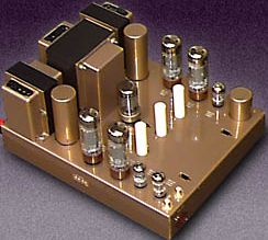
The output transformer is the heart of a valve amplifier. The right pic shows a stereo Leak amplifier. The two output transformers are rotated 90deg to the power mains transformer to avoid picking up induced hum from the mains transformer external magnetic field. Output transformers contribute most of the distortion in a valve amp and have a limited bandwidth.
Valve amp manufacturers purchase transformers from transformer winding companies. Transformer winding is an extension of the fitting and turning industry. Few people working in transformer winding companies have a knowledge of electronics or valve amps. Most valve amp manufacturers have a basic academic understanding of output transformers, but often have a limited or incorrect understanding of the physics of transformers or how they are made.
Academic formulas for calculating the design of output transformers is available in many text books and websites. There is no need for this page to repeat academic information that is readily available. This page gives an overview of the physics that governs the performance of output transformers and helps give a perspective that academic text often omit.
Output transformers are the highest cost and most labour intensive part of a valve amp to make. Each output transformer, depending on size, takes approx 1 to 2 hours to wind, assemble with laminations, heated in an oven, dipped in resin and baked overnight, cleaned, painted, external leads connected, dress caps fitted, packaged and sent to a valve amp manufacturer. A tedious task to say the least. The right pic is a simple analogy of an output transformer.
B+ historically represents battery. B+ is the supply voltage to the centre tap (CT) of the primary windings of the output transformer. 560V DC supply is connected to the CT of the primary winding. The amplified audio from the 2 output valves push-pull is in opposite phase 180deg. 300VAC + 300VAC = 600V AC is across the primary winding.
Depending on the transformer design there may be 2,000 turns of wire in the Primary and 90 turns for the Secondary winding. 22:1 step down ratio. 600V AC / 22 = 27V AC into an 8&Omega speaker is 90 W.
The primary and secondary windings are isolated. The iron core is magnetised by the AC current in the primary winding and the AC magnetism is passed into the secondary winding generating an output voltage to drive the speaker.
 The turns ratio between the windings adjusts the secondary voltage. Only AC can pass through a transformer. It is not possible for DC to pass through a transformer.
Copper mass. The total mass of copper wire is divided 50/50 approx between primary and secondary. Often the primary has slightly more mass. In the example transformer the primary has 2,000 turns of thin wire, whereas the secondary has 90 turns of thick wire.
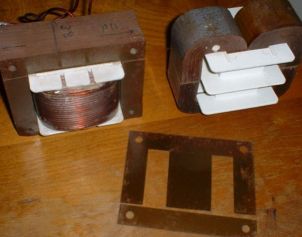
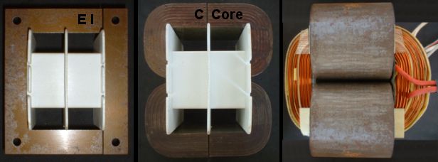
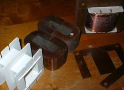
E I and C core. The majority of power and output transformers in valve amps are E I construction. The right pic shows the thin E I mild steel laminations that are stacked together to assemble the core. The transformer next to the E I is a C core which can be used for the same size bobbin. Bobbins can be open or have a centre division. The C core is approx 20% more efficient compared to the best quality grain orientated E I laminations. The square shape of the E I laminations is not an efficient conductor of magnetism. A % of the induced magnetism is spewed outside of the core and lost. A further % is lost as eddy currents within the laminations which causes the laminations to get hot. E I mains power transformers are noticeably hot when touched. C cores are an efficient conductor of magnetism, but C cores do not have an aesthetic square shape and are more difficult to mount onto a chassis. C cores are mostly used in industrial electronics and were approx twice the cost of E I laminations. Today, C cores are only slightly more expensive than E I laminations and it makes no sense not to use the superior quality C core in all output transformers, including power transformers.
It is essential to fill the window space with copper wire. Once the number of turns is calculated then the thickest wire is selected to fill the window space. Any space not filled with copper wire causes magnetic energy being lost, described as leakage inductance, resulting in reduced performance.
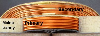
Mains power transformer. The primary is wound on the bobbin first then the secondaries are wound on the outside of the primary. There are required safety standards for the minimum thickness of insulation placed between the primary and secondary windings. A mains transformer only functions at a fixed primary voltage and frequency (120V AC 60Hz) or (240V AC 50Hz) depending on the standard of the country.
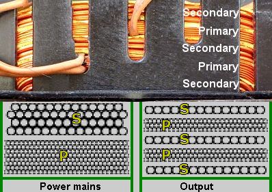
Output transformers function over a wide range of frequency and voltage. The primary and secondary windings must be split up and inter-leaved. Secondary - Primary - Secondary - Primary etc. Interleaving the primary and secondary enables the transformer to achieve a high frequency response. As a general rule, the greater the numbers of primary and secondary interleaving the better the high frequency response. A physically large transformer has increased capacitance between windings which causes phase shift and restricts the high frequency response. A smaller transformer with less turns favours the high frequency response.
Total turns. Increasing the total number of turns in an output transformer increases the inductance (magnetic efficiency) which improves the bass response. But, increasing total turns requires a smaller wire gauge which increases DC resistance and reduces the power output of the transformer. Calculating turns ratio, maximum number of turns and interleaving is a balancing act.
The traditional approach is to minimise the total number of turns and core mass, restricting the bass response in favour of improving high frequency response. The argument for justifying the approach of minimising core size and total number of turns also minimises cross capacitance, keeping phase shift to a minimum, which allows a greater amount of negative feedback to be applied, thereby improving the pseudo academic figures of lower distortion. Valve amps were part of the vinyl era where deep bass caused the needle to jump off the record. Most hifi valve amps had a rumble filter to reduce sub-bass. The majority of speakers were approx 6dB to 10dB more efficient and larger than most speakers boxes today. A few watts was very loud.
Inductance. The real reason for minimising the output transformer size was/is to minimise the cost of making the transformer. An inductance of 20 Henries is often insufficient. 40 Henries or higher is required for an output transformer to deliver full power below 40Hz. The mathematical inductance can be academically calculated, but in the real world the physics of inductance in output transformers is not a fixed value. For a full range output transformer the aim is to get as much inductance as possible regardless of what the academic number ends up being.
At bass frequencies the speaker Fs (fundamental resonance) raises to approx 20 to 30Ω. Valve amps naturally have a high output impedance and the output voltage will automatically rise in an attempt to maintain constant power to the speaker. As the output voltage rises, especially at high power, a transformer without sufficient inductance at bass frequencies can easily saturate, creating intense distortion. To prevent core saturation the primary turns should be the maximum number and the core mass must be as large as possible for a given chassis size.
In the past when only valve technology existed, materials were expensive in comparison to labour. An output transformer for a 100W valve amp was approx $10 to $20 in quantity. $5 for materials, $5 for labour and little profit. The majority of output transformers were the minimum size, made from the least expensive materials. Only a few high-end valve amps had output transformers that were made with the best quality materials.
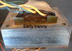
Paper layering. Early transformers for valve amps mostly used the less expensive, lower voltage rating enamelled copper wire and thick impregnated paper insulation between each layer of winding. Paper layering enabled the transformer to be wound at high speed by automated machines, reducing labour and keeping costs under control. Poor insulation of the paper and poor enamel coating on the wire enabled flashover to occur between windings.
Extreme high voltages are generated across the primary winding if the speaker is disconnected while music is playing. Flashover between windings was a major problem with valve guitar amps.
A disproportional % of window space is consumed by paper layer insulation which limits the total number of turns to enable the transformer have sufficient inductance to obtain a good bass response. With a restricted window space the wire has to be thinner which causes further losses in the DC resistance of the wire. The space occupied by thick paper insulation causes leakage inductance, reducing efficiency of the transformer.
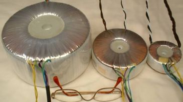
Modern materials. High voltage thin polyester Mylar, Kapton and Nomax insulation including high voltage hardened enamel wire (used in electric motors) was readily available from the mid 1960's. Using these higher quality insulating materials does not require paper layering between each layer of winding. The above pics of modern mains and output transformer windings shows the thin high voltage insulation is only used between primary and secondary windings, minimising the space occupied by the insulation and enabling the maximum mass of copper wire to fill the window space.
But, very few valve amp manufacturers were/are aware of the physics of output transformer design, therefore the higher quality insulation and high voltage enamel coated wire including C cores were rarely used. Output transformers were made to a budget and when solid-state technology arrived the era of valve technology came to a close.
Today, an output transformer for a 100W valve amp is approx $50 to $100 for materials, $100+ labour, 100%+ profit. End price approx $200 to $600. But because of alchemistic beliefs in imagined magical perceptions of bygone brand names and components, many output transformers today are still made using the same methods and low cost materials as in the past.
Output transformer types
In most output transformers the windings are layer wound across the bobbin. Interleaving the primary and secondary windings enables the transformer to achieve a high frequency response. The primary windings are connected in series, the secondary windings are mostly connected in parallel. The secondary windings often have taps to adjust the output impedance for 8Ω or 4Ω speakers.
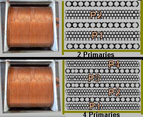
A cheaply made output transformer (used in many tube guitar amps), will have 2 primaries with a single secondary between the primaries (P1, S, P2,) or have 3 secondaries interleaved between the 2 primaries
(S, P1, S, P2, S,) as shown in the right pic.
A better output transformer will have 4 primaries with 3 secondaries interleaved between the primaries
(P1, S, P2, S, P3, S, P4,) as shown in the right pic.
Some high quality output transformers may have as many as 8 primaries interleaved with 7 to 9 secondaries. The greater the number of primary and secondary windings, the better will be the high frequency response, but the longer the time it will take to wind the bobbin.
The right pic is a circuit showing the series connections of 4 primary windings. P1 is the first winding on the inside of the bobbin whereas P4 is the last winding on the outside of the bobbin. P1 and P4 are referred to as outer windings because the other windings are in-between.
Cross-connection. The primary windings are alternately cross-connected in series around the secondaries (outer P1 - inner P3 - inner P2 - outer P4). Alternate cross-connecting the primary windings enables the physics of the transformer to be closely balanced and the induced magnetic current to be distributed equally into the secondary windings.
The aim is to balance (as close as possible) the primary secondary windings (equally) on both sides of the centre tap CT. However, balancing can not be perfect because the inner and outer diameters (circumference) of the windings are different. Wire length and DC resistance of P4 is greater than P1. Increasing the number of primary and secondary interleaving has been the traditional approach to improve the balance and performance of an output transformer.
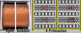 Fully balanced windings can be achieved by taking a lateral approach to how the bobbin is wound. 2 Primaries and 3 secondaries are wound on each half of a split bobbin. This gives a total of 4 primaries and 6 secondaries. The primary windings are series cross connected on opposite sides of the split bobbin
(P1, P2, CT, P3, P4).
 Very few output transformers are constructed using this lateral approach.
Why this lateral approach of using a split bobbin to achieve a fully balanced output transformer was/is not seen by the majority of transformer winding companies is a mystery. The answer is possibly tradition and conformity and that very few electronic designers, especially audio valve amps, directly participate in the design and construction of transformers.
27kg bass transformer. The right pic is a 27kg (60lb) bass output transformer, fully balanced split bobbin. Yes, you read correctly. 27kg is possibly the largest output transformer ever constructed. This output transformer was constructed for experimental reasons. The inductance was higher than the test equipment could accurately measure. The transformer is capable of delivering 1,000W below 10Hz. However, the practical application is for 4 KT88's in push-pull parallel 200W. These large output transformers can be made available to valve enthusiasts who wish to have the ultimate active sub-bass valve amplifier.
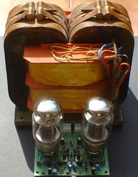
Pi windings. The Greek letter Π is the symbol for transformer windings that are rotated 90deg in a bobbin. Π windings are sandwich assembled. The below pic is an experimental valve amp with Pi wound output transformers. The final design had 8 Primaries sandwiched between 9 secondaries. Pi wound transformers are 100% symmetrically balanced and have a high frequency response x 2 greater than a conventional layer wound output transformer.
Pi winding is commonly used in ferrite core transformers that transfer energy at very high frequencies, as seen in switch mode power supplies and Rf amplifiers. Pi winding is also the perfect method to construct an audio output transformer. Pi winding output transformers are not known to have been used in audio valve amps. A possible reason is the high tooling and assembly costs. Also, the marketing of audiophile products, particularly tube amps, is driven by brand names, romantic nostalgia and reviews, not by engineering or performance.
 Toroidal output transformers are now being used in some tube amps. In the past, toroidal transformers were x 2 more expensive than EI transformers because of the high cost of toroidal winding machines. Today, labour is expensive by comparison to the cost of a toroidal winding machine. Many transformer winding companies now have toroidal machines. E I and toroidal are now approx the same cost to construct.
Toroidal transformers have superior magnetic coupling between windings, but a toroidal core can easily saturate at low frequencies creating intolerable distortion. Therefore, the mass of the toroidal core has to be larger than a conventional E I transformer (for the same power) to avoid any chance of saturating the core. Toroidal cores are unforgiving of any DC or AC audio imbalance in the primary windings. Both output valves must be perfectly biased with exactly the same current and have exactly the same gain when driven. Providing these conditions are met, a toroidal transformer will outperform a conventional EI transformer.
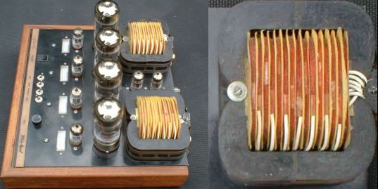
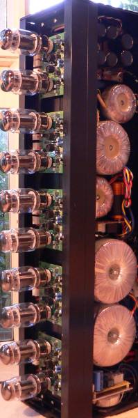
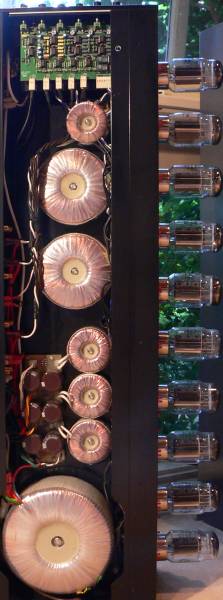
4-way active valve tower. The below pic is a 4-way active valve tower using toroidal output transformers as in the above pic. There are 5 100W ultra-linear amps using KT88's. The 2 amps at the bottom of the chassis are paralleled to give 200W. The chassis is divided down the centre. One side of the chassis (left side of pic) is the power supply. The power supply also uses toroidal core transformers. The other side of the chassis (right side of pic) are the toroidal output transformers.
|
Right pic shows output transformers and active crossover → High-frequency transformer (5kHz - 50kHz)→
The 3 small toroid chokes mounted above the large bass output transformer are for filtering the B+
↑ The small top toroid power transformer (+-20V and +-100V) is for the electronic crossover and driver circuits of KT88 output valves. Below the top small power toroid is the power toroid and toroid choke for the 12.6V DC filaments heater supply. ← The 2 large toroid transformers create the 560V B+ supply. The B+ supply is constructed from 3 X 188V supplies in series. ↓ Power turn on management. Total mass 60Kg approx. |
|
The 4-way active crossover and driver stages are solid state to ensure a perfect distortion free symmetrical signal is delivered to the output valves. Each KT88 has dual LED monitoring to enable the quiescent current through the KT88's to be calibrated.
Output transformer application
Valve amps require perfectly matched output valves in order to give the best performance. This is similar to having balanced pistons in a vehicle engine. It is essential that the quiescent current through the output valves be calibrated exactly. A 10R resistor is placed in series with each cathode. The -bias voltage to the grids is adjusted so 500mV appears across each 10R resistor. 500mV across 10R is 50mA. The valves are then driven to full power and the current through the valves will increase to approx 150mA. Both valves must be perfectly equal in both quiescent and full power condition. Any imbalance of current between the valves will result in the iron core of the transformer being partially DC magnetised. The inductance will be reduced, the bass response will be diminished and the core will readily saturate at bass frequencies.
Tetrode. Many early hifi valve amps and almost all guitar valve amps are configured in tetrode operation. In tetrode operation the screens of the output valves are connected to a second B+ filtered supply voltage from the power supply.
The primary of the output transformer is connected to the anodes of the power valves. Transformers designed for tetrode operation only need 3 wires from the primary. CT centre tap to the B+ supply and 2 wires to the anodes. Transformers designed for tetrode operation (guitar amps) are often made as cheaply as possible, however there are exceptions.
Ultra-linear. Output transformers designed for ultra-linear application are often made from the highest quality materials and have multiple primary secondary interleaving. The screens of the output valves are connected to the primary windings. Ultra-linear provides the same high power as tetrode configuration with superior power and inter-modulation performance than a triode configuration. The power supply for ultra-linear amps must be of high regulation, smooth and ripple free.
The original academic text stated that the screens should be connected to a 42% tap position of the primary winding, to achieve maximum power. The original text only refers to graphs and did not take into consideration how an output transformer is wound. It is difficult to mechanically achieve perfect symmetry with 42% tap positions on both sides of the centre tap, however 50% can easily be achieved. If a trade off has to be made, the mechanical symmetry of the primary windings, must come first. Also, the theoretical difference between 42% and 50% is too small for any auditory or measured difference to be detected.
Output transformer parameters
The distortion figures and frequency response of valve amps are often specified at 1W. Most output transformers can easily achieve a bandwidth of 20Hz to 20kHz at 1W. But this bandwidth is rarely achieved at full power. The low frequency response at full power is directly proportional to the number of primary turns and mass of the iron core.
Above 2kHz the iron core has little effect. The high frequencies response is directly dependant on the interleaving of the primary and secondary windings. However, if the transformer has a large core and a large number of primary turns enabling it to achieve sub-bass at full power, then the large area of the windings causes increased capacitance between primary and secondaries which restricts the high frequency response. Therefore a small core with less turns favours the high frequency response.
 The bobbin and core in the right pic is for a 100W output transformer, 1.5in (one and a half inch) core with an approx 2 inch stack. Mass approx 3kg. The majority of output transformers of this size have approx 2,000 primary turns. With skilled winding technique and compacting the wire tightly, the primary turns can be increased to 2,500 or 3,000. The total DC resistance of the primary should not exceed 100R, 0.36mm wire or greater can be used. The parallel secondary windings can be 1.1mm or 1.2mm. Secondary DC resistance approx 0.1R.
There is no one way to wind the perfect transformer. There are a few highly skilled people who wind transformers and will have various techniques for achieving the objective. The inductance of the transformer will vary depending on core mass and quality, and number of primary windings. The aim is for the inductance to be as high as possible. The below pic is a complied list of basic formulae for those who wish make output transformers.
Academic formulas for calculating output transformer design are available in many text books and web sites. Those who make output transformers will already be overwhelmed by the math and there is no need for this page to repeat academic information that is readily available. This page is intended to give an overview of the physics that governs the performance of output transformers, from a perspective that academic text often omit.
Impedance ratio
Understanding impedance ratio between primary and secondary is difficult for those who are technical and almost impossible to understand for those who are not. Hopefully this explanation will make it easier for anyone who is interested.
Academic text states that a pair of KT88's in push-pull class AB, from a B+ 560V supply voltage will deliver 100W. Under this condition the output transformer primary impedance is stated as 4k5Ω. The impedance of 4k5Ω is an academic figure and represents the highest plate to plate impedance that will enable 100W to be obtained. (plate to plate simply means anode to anode). This academic figure of 4k5Ω assumes 100% transformer efficiency with zero losses.
A pair of KT88's will rarely achieve 100W in the real world. The average is 80W to 90W. Also the plate to plate impedance can vary between 3kΩ to 5kΩ with little change to the available power.
Our sample output transformer has 4 primary windings (600 turns per winding) a total of 2,400 turns.
4k5Ω plate to plate / 8Ω speaker = 562.5. √562.5 = 23.7 turns ratio.
2,400 primary turns / 23.7 = 101 secondary turns.
This academic process requires the formula to be repeated over and over for each change in calculation. Another way to view this process is through the math related to the output transformer physics. The voltage ratio between primary and secondary is the same as the turns ratio.
A general rule for push pull class AB valve amplifiers. The RMS voltage across the primary winding is 1.1 x B+ supply voltage (at full power).
1.1 x 560V DC = 616V AC
100W into an 8Ω speaker = 28V RMS
616 / 28 = 22 turns ratio.
2,400 primary turns / 22 = 109 secondary turns.
There is a small difference of 8 secondary turns between the two calculations. This second formula does not look at the plate to plate impedance. Therefore, which calculation is more practical to use? By reversing the last calculation of a 22:1 turns ratio by the first formula we can see what the reflected plate to plate impedance has been reduced to -
22 x 22 x 8Ω = 3,872Ω plate to plate impedance.
A difference in turns ratio (23.7:1) (22:1) results in a small difference of 8 secondary turns. This small difference causes a large change to the academic reflected plate to plate impedance.
 The right pic shows that an 8Ω speaker has an average impedance well above 8Ω. Two and three way hifi speaker boxes attempt to keep the overall impedance as close to 8Ω as possible. Also, the leads connectors add extra resistance.
Output transformers are not 100% efficient. Core losses, leakage inductance and DC resistance of the copper wire all contribute to increasing the overall reflected plate to plate impedance higher than the academic figure. Therefore, the second formula closely represents real world conditions, however it is wise to be conversant with both approaches and cross check each method.