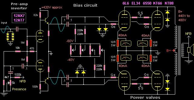
Fender and Marshall were/are the most renown and copied amplifier brands. The most popular of the larger models including the clones had/have 4 output valves in parallel push-pull that produce 60 to 100 Watts. No allowance was/is made in the majority of guitar and bass amps for ease of service. In most cases the output valves are unable to be readily calibrated and balanced. This is similar to a vehicle engine where the designers applied no thought for the engine to be serviced or tuned. Also the limited circuitry can not drive the output valves symmetrically unless modified. Most valve guitar and bass amps rarely perform at full capacity, which inadvertently protects the speakers. Similar to a vehicle that cannot exceed the speed limit due to its mechanical limitations.
These statements are not intended to be derogatory, but statements of fact. The same can be said of almost any mass produced product. Many who service their own motor vehicle can be heard cursing those who designed it. Computer operating systems are another example. For any product to be successful in a capitalistic society, the manufacturing cost must be a fraction (1/10 to 1/100) of end user price. This paradox insures that any successful marketed product will always have design contradictions.
There are many web sites and books that have information on servicing valve guitar amps. This page will focus on resolving some of the contradictions and hopefully give a broader understanding of guitar amp design and service. Early Fender and Marshall 60 Watt to 100 Watt models commonly used by professional musicians will be used as examples.
- Biasing output valves
- Matching output valves
- Inverter balance
- Output stage protection
- Screen regulation
- Power supply
Biasing output valves
Providing the amp circuit is correct and there are no component faults, a valve amp performance is dependant on the correct balancing and matching of the output valves. This is similar to having balanced pistons in a vehicle engine, plus the ability to tune the engine. For many years both Fender and Marshall did not provide any method for output valves to be independently calibrated or balanced. All that is provided is a crude overall -bias Voltage adjustment.
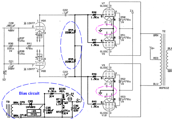
The above circuit shows that the -bias Voltage is connected to all the Grids of the output valves. Only a single overall -bias Voltage adjustment is provided, but no individual adjustment is provided for each output valve. The Cathodes of the power valves are connected directly to earth- chassis. It could not have been possible for these amps to have left the factory with output valves that were calibrated and matched, therefore the performance of these amps would have been random.
It appears Fender and Marshall may have depended on output valves being identical when purchased. Or they had a means for matching valves before they were plugged into the amps. Or they were technically ignorant of understanding the physics of output valves and the need for the valves to be independently calibrated. The opinion of many senior electronic engineers is the latter hypothesis was most likely. Fender amps have only recently been made available with independent bias calibration for the output valves.

The above 2 bias circuits are typical of many early Fender and Marshall amps, however there are subtle variations between models. The -bias Voltage should appear immediately the moment an amp is turned on, and the -bias Voltage be perfectly smooth, ripple free. But the circuits above do not achieve this. A simple 1/2 wave rectifier (1 diode) is the cheapest method to create a -bias Voltage and a 1/2 wave rectifier causes maximum ripple. A bias circuit should have 4 diodes as a bridge.
These simple 1/2 wave rectifier circuits are slow to charge up to full Voltage. This is not a problem when the amp if first turned on, because it can take 30 to 60 secs for the output valves to reach full temperature. But when the mains power is accidently interrupted after the amp is hot, the output valves will go into full conduction untill the bias has again reached full Voltage. In Marshall amps, the HT fuse is sometimes blown when this happens. Full current conduction in output valves causes Cathode stripping, damaging the valves.
Matching output valves
When purchasing matched valves, do not trust that they are matched. The only advantage in purchasing matched valves is that they may have been checked that they work, and if one is faulty the distributer may replace it without question. The only way to insure power valves are identically matched is to do it yourself, or find someone who is technically competent to do it.
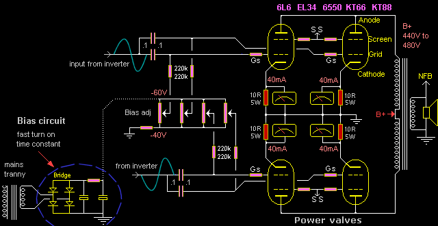
The above example circuit shows independent bias adjustment for each output valve. A choice can be made to add independent bias adjustment, or not. 4 identical 10R 5 Watt resistors must be placed in series with each Cathode to monitor the Current flowing through each valve. The 10R bias monitoring resistors should be wire wound (5 Watt). Wire wound resistors are +-20%, therefore the resistors should be individually measured and matched.
Approx 10 to 20 output valves are required to select 4 that can be closely matched. When 4 closely matched output valves have been selected, the independent bias adjustments can trim the valves so exactly the same current is flowing through each valve. Adjust the -bias Voltage for 400mV across each 10R resistor.
400mV = 40mA. B+ 460V x 40mA = 18.4 Watts heat dissipation per Valve.
Pairs. If using the existing single bias adjustment, put the valves in pairs, so the added current (80mA) through the left pair = the added current (80mA) through the right pair. Assuming a test bench with an audio generator, oscilloscope and the amp is connected to a dummy load. Adjust the tone controls for minimum phase shift to obtain a sine wave (approx 400Hz). Turn the amp up just under clipping and check that the Voltage across each 10R resistor has risen equally to approx 1V.
Flashover. A faulty valve can have air leakage at the base and flash-over occurs between the elements. The physics of flash-over is similar to lightening. At the moment of flash-over a negative resistance is created that magnifies the current. A normal 1/2W or 1W resistor can be vaporised, depositing a carbon film throughout the amp. Wire wound resistors will survive or act as a fuse.
Inverter balance
It is essential that output valves are driven with perfectly balanced 180deg signals. However to achieve this requires 2 pre-amp valves. Single valve, cathode coupled Inverters, of which there are many variations, are used in almost all valve guitar amplifiers. The only advantage of a cathode coupled inverter is that it amplifies and creates two quasi balanced 180deg signals within one twin triode (12AX7 or 12AT7). This enables the minimum number of valves to make an amplifier, hereby economically rational for mass production when needing to control costs.
But, single valve, cathode coupled inverters can not create 2 consistent 180deg signals. Depending on the difference between each triode in the inverter valve, the outcome can be random. There appears to be no amplifier that enables the outputs of a cathode coupled inverter to be calibrated.
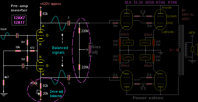
Inverter calibration. The Anodes of the inverter are wired with slightly different value resistors (82k and 100k) as a crude attempt to compensate for the imbalance between the outputs. A simple modification by substituting the 100k with a 82k and 20k trim, as in the circuit above, to enable the output signals to be calibrated. The aim of the inverter balance adjustment is to achieve identical current through each pair of output valves when the amp is driven to full power. This calibration procedure should be repeated approx each 6 months, if the amp is being consistently used.
 Load imbalance. Cathode coupled inverters have another major problem. The 2 x 220k resistors, that supply the -Bias Voltage to the Grids of the output valves, represent a load to the output of the inverter, so much so, that the inverter struggles to drive large output valves 6550, KT88s to full power. One solution is to increase the 2 x 220k to a higher value. But, 220k bias resistors can not be increased to a higher value because the Bakelite base of many output valves is not a good insulator at high temperature.
Bias creep. Many amps have poor ventilation (especially combo amps) and the output valves get excessively hot. Current can leak between Grid (pin 5) and Screen (pin 4). Current leakage between the pins at the valve base causes the -bias Voltage to reduce, which in turn causes the quiescent current of output valve to increase, which in turn causes the valve base to get hotter. Many tube manufacturers recommend that the maximum value of the bias resistor should be no greater that 100k, for each output valve. 47k for 2 output valves in parallel. In the above circuit the bias resistor is 200k for each pair of output valves, which is equivalent to 440k for each valve.
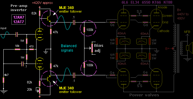
Emitter followers. A simple modification is to add 2 x MJE340 or equivalents transistors as emitter followers from the Anodes of the Inverter valve. Emitter followers act as buffers, providing a lower impedance drive for the balanced signals. This modification will enable the balanced outputs to remain symmetrical at full level and the bias resistors can be reduced to 100k.
Output stage protection
When output valves are driven into hard clipping, the inverter signal alternately drives one output valve into cut-off and the opposite output valve into full current saturation. The driving signal that causes one output valve to be driven into saturation also conducts grid current which charges up the 0.1uF coupling capacitor, temporarily increasing the -bias Voltage. By the second alternate swing of the driving voltage from the inverter, the -bias Voltage to the output valves is driven up so much by the DC charging of the 0.1 coupling capacitor, that a "dead time" can occur between the small time when each output valve is cutoff and the other is driven into saturation.
During the minute period of "dead time" the current through the output tranny is instantaneously zero. A back EMF high Voltage is generated across the tranny windings (2kV to 5kV) which can -
1. Cause flash over in the output valve base or socket, between pin 3 Anode and pin 2 heater.
2. Cause flashover between the elements of the output valve, destroying the valve.
3. Cause flashover between the windings of the output tranny, destroying the tranny.
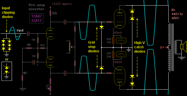
Three simple circuit additions using diodes can help protect the amp and enable a cleaner over-drive.
1. Input clipping diode circuit will have to be designed to suit each model of guitar amp. An average diode has a forward turn-on Voltage of approx 0.7V. Under the forward turn-on Voltage a diode is an open circuit. By putting diodes in series, the turn-on Voltage can be adjusted. Because the audio input signal is AC, two diode strings in opposite directions will be required. Low Voltage zeners (back to back) can also be used. The aim is to clip the input signal to the inverter valve to co-inside with the onset of the output valves being driven into clipping. Also the -bias Voltage will remain stable reducing the possibility for a "dead time" to be created.
2. Grid stoppers. These diodes will minimise output valve grid current occurring during over-drive. Also these diodes help protect the surrounding circuitry if an output valve flashes over internally.
3. Catch diodes. It is essential to put high Voltage catch diodes from the Anodes of the output valves to ground chassis. These catch diodes will short out any high Voltage back EMF that appears across the primary winding. Catch diodes will not influence the amps behaviour of performance.
Faulty output tranny
A high Voltage flashover can occur across -
- the output tranny primary to primary windings, or across primary to secondary windings.
- pins 2 (heater) and 3 (Anode) at the valve base, or the valve socket.
- internal elements inside an output valve.
Caused by -
- Hard over-drive causing bias "dead time" between output valves.
- Guitar lead being pugged or unplugged at the guitar, causing a loud BURP.
- Volume turned up full without the speakers connected.
Resulting in -
- blowing the HT fuse.
- harming output valves.
- destroying output tranny.
If the HT fuse and Mains fuse have been replaced with nails -
- the rectifier diodes will be destroyed.
- mains tranny will melt down.
- pungent smell of burning resin, accompanied with smoke.
Suppose all the destroyed components are replaced, and there appears to be no short-circuit across the primary to secondary windings of the output tranny, But the amp works with reduced power, sounding shallow, bass response almost non existent. These symptoms are likely to be the result of flashover across the primary winding that caused few of the primary turns to be shorted. An output tranny can be tested in many ways. Shorted primary turns causes a large loss of Inductance. The simplest method is an Inductance meter. But this test requires knowing the original Inductance of the tranny. "What are other procedures for testing the output tranny for shorted primary turns?"
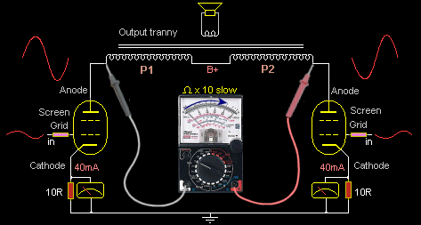
1. Current test. Using an audio generator (400Hz) and an oscilloscope at the speaker output, without the speaker connected. Turn up the level slowly (under clipping) while monitoring the Voltage across the 10R Cathode resistors. The Voltage across the 10R resistor should not increase. If the Voltage across the 10R increases then current is flowing through the output valves which shows that the output tranny has shorted primary turns.
2. Ω Test. Remove the output valves, speaker lead and mains lead. An analogue multi-meter set to Ω x 10. First calibrate the meter to read 0Ω. Also note how quickly the needle moves when reading 0Ω (FSD full scale deflection). Check that the resistance reading between CT and each Anode is the same or very similar (approx 50Ω). If there is a significant resistance difference between CT and each Anode then the side which has lower resistance reading has shorted turns.
3. Inductance test. Place the multi-meter leads across the Anodes. The needle should delay moving, then slowly start to increase speed untill it reaches approx 100Ω. Reverse the meter leads and repeat the observation, then reverse the meter leads and repeat the observation again, approx 3 times. If the needle hesitates before starting to move slowly, this shows the tranny has Inductance and is possibly OK. But if the needle moves quickly, similar to reading a Resistor, then the tranny has little to zero Inductance, showing that the tranny has internal shorted primary turns.
The best way to do the Inductance test is with a good output tranny in another amp that is working well. Practice doing the analogue meter reading with the good tranny first. Carefully note the DC resistance of the primary windings between CT and each Anode. Then Anode to Anode. Pay particular attention to the delayed reaction of the needle and the rate at which the needles moves. Then compare these results with the suspect faulty tranny.
4. Mains V test. Disconnect the speaker lead. Disconnect the CT and connect a mains lead across the primary (Anode to Anode) with a 100R in series. Turn on the 120V / 240V mains power. No Voltage should appear across the 100R. If a small Voltage appears across the 100R that means the tranny has low Inductance and possibly shorted primary turns. If after approx 4 hours the tranny gets warm or hot, then the tranny has shorted primary turns.
Screen regulation
Guitar amps evolved as adaptations of large domestic HiFi amps. Almost all valve guitar amp designs exceed the maximum screen Voltage ratings of the valve specifications. Output valves are very forgiving of exceeding maximum Voltage limits. But when guitar amps were first designed, it was inconceivable that they would be driven at full power into over-drive. When output valves that have screen Voltages beyond the specification limits, are driven into over-drive, the valve is partially damaged and its life reduced to less than 1/10.
400V Screen. In tetrode operation (including Pentodes) the screen Voltage influences the gain and performance of the Valve. Therefore the screen Voltage should be stable or regulated. Screen Voltage should never exceed 400V. (Ultra-linear amps with KT88s are an exception) The screen is not designed to conduct current. Any current through the screen should be minimal. When output valves are driven to full power, with a screen Voltage greater than 400V, the screen draws excessive current, and extra excessive current when driven into overdrive, permanently damaging the valves.
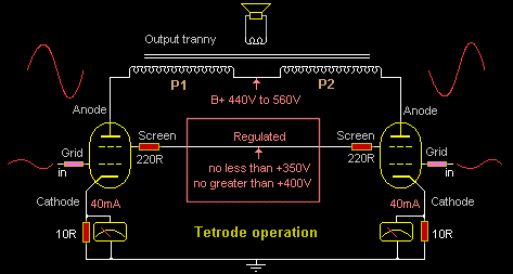
360V is the minimum screen Voltage that will enable most commonly used output valves 6L6, EL34, 6550, KT88 to achieve maximum specified power, with minimum current through the screen. A screen Voltage less than 350V will limit the valve achieving full power. A screen Voltage above 400V will not enable an output valve to achieve greater power than specified.
Screen resistor. Resistors should always be placed in series with the Screens as close to the valve pin as possible. This helps limit the excessive current into the Screen at full power and also restricts parasitic Rf oscillation. Screen resistors should be 5 Watt rating, between 220R to 470R. If an amp is being constantly driven into over-drive, 1k Screen resistors will provide extra protection for the valves, but with a small reduction in output power.
Various models of Fender and Marshall amps have a B+ supply Voltage between 440V to 530V. A 400V regulator circuit can be simply added by using a high Voltage power MOSFET (600V), as in the circuit below. The regulated 400V supply also gives superior stability for the lower decoupled supply Voltages to the Inverter and pre-amp valves.

The high Voltage power MOSFET must be bolted to the chassis with added insulation. A B+ of 440V to 480V can be connected directly to the Drain of the MOSFET. Some Marshall amps have a B+ of 530V approx. Therefore a 2k2 5 Watt wire wound resistor can be placed in series with the Drain to reduce the Voltage across the MOSFET. The 2k2 or a selected value, will dissipate some of the heat enabling the FET to be cooler. The 400V Gate reference is supplied by 2 x 200V Zener diodes. The 10k resistor in series with the Gate keeps the FET parasitically stable. The 12V zener diode from Source to Gate insures the Gate Voltage can not exceed its maximum rating. The output Voltage at the Source will be slightly less than 400V, depending on the Gate to Source forward bias.
With a regulated Screen Voltage the amp's performance when driven into over-drive will be smooth and controllable. Many, if not all the un-desirable inter-modulation artifacts (power supply ripple) will have disappeared. The amp will run cooler and output-valve life will be greatly extended.
Power supply
When guitar amps were first mass produced in the 1950s the largest problem was sourcing good quality components, especially Electrolytic capacitors for the power supply. By the mid to late 60s, component technology had vastly improved and there was no excuse for every guitar amp manufacturer not to use the best components that were and are now available.
Heat is the enemy of electronic components especially Electrolytic capacitors for the power supply. Not allowing good ventilation and placing Electros close to output valves insures that the Electros will have a short life. Checking and replacing the B+ Electros is an essential practice of good serving. The quality of a power supply is directly dependant on the size of the Electros (minimal ripple). To achieve minimal ripple the B+ Electros should be 470uF, 105deg C (not 85deg C). Replace the existing B+ Electros with the largest capacitor uF size that can be fitted within the space available. Power supply designs can vary between models. But many manufacturers tend to maintain design practices for which no rational reason is given.

In the Fender circuit above, the heater filaments, -bias Voltage and 440V HT is always on. The standby switch simply disconnects the B+ supply from all the valves. But when the standby switch is turned off, (after the amp has been running), the DC current through the TR2 choke is abruptly disconnected which causes a high Voltage back EMF transient to be generated across the choke. A simple addition of 2 catch diodes solves this problem.

The above Marshall circuit shows that the standby switch disconnects the AC from the mains tranny to the bridge rectifier - "Why?" One possibility is, that the manufacturer possibly intended the amp to be turned on for a minute, giving time for the heater filaments to come up to full temperature, before the standby switch is turned on. A possible reason for doing this is to provide some protection for the B+ Electros which are already at their Voltage rating limits when the amp is running.
If the amp is turned on (when cold) with the standby switch in the closed position, the B+ Voltage will rise approx 10% to 15%% higher, untill the output valves warm up and start to conduct current. During this initial warm up time , the Electros may be over-Voltaged and therefore damaged. This represents that the manufacturer purchased the cheapest Electros possible. Therefore the Electros should be replaced with high quality, higher Voltage rating and the largest uF size that can be fitted in the given space.

The above modified circuit shows the B+ Electros have been replaced with 470uF and the MOSFET Voltage regulator for the 400V Screen supply has been added. Voltage regulation for the screens (using a valve) should have been standard in all 60 to 100 Watt guitar amp designs from the mid 60s. With a Screen Voltage regulator there is no need for a choke. The simplest standby function is to switch the 400V to the Screens only. Why this simpler method, to switch the Voltage to the Screens, was/is not used in all amp designs, is a mystery.
Modified Guitar amp
