

A solid-state valve amp is an oxymoron. But, we can ask the question as to why little interest or research was done by guitar amp manufacturers in understanding the physics of amplifier behaviour when a valve or solid-state amp are driven into over-drive.
The majority of guitar amp manufacturers tend to copy each other, including each others technical mistakes. Many theories have been put forward about this bizarre copy-cat behaviour. A possible reason is that the industry has a forever child like mentality. Sales are driven by stage image and brand names, therefore technical research has no economic relevance, so why bother.
This page describes how a solid-state guitar amp can be made to emulate and outperform a valve amp. The technical explanation about the behavioural difference between valve and solid-state amps is fully covered in the solid-state and valve amp chapters. This page begins with expecting the reader to have read the other chapters first, and also to have a basic technical understanding of valve and solid-state amps including speakers.
Some technical people may find this information confirms what they already know, others may find this information challenging and difficult to comprehend. The principles outlined are deliberately generalised to allow the overall concepts to be understood. Any competent design engineer will be able to adapt these concepts allowing creative variations within their design detail.
- Current drive conversion.
- Guitar over-drive power control.
- Bass transient headroom.
- EQ management.
Current drive
Valve amp power is directly proportional to speaker impedance.
The above pic shows that the output power of a valve amp tends to be directly proportional to the speaker impedance. The power increases as the speaker impedance increases. A valve amp acts as a limited constant current source. A solid-state amp is the opposite, power decreases as the speaker impedance increases. A conventional solid-state amp acts as a constant voltage source. Can a solid-state amp be made to do exactly what a valve amp can do ? - "Yes".
Solid-state amp power is inversely proportional to speaker impedance.
A conventional solid-state amp is configured with the negative feedback taken directly from the output of the amp and connected through R1 to the -inverting input. The ratio of R1:R2 controls the gain of the amp. The speaker is separate from the amp. It makes no difference at the output of a solid-state amp if a speaker is connected or not. The output of the amp behaves as a constant voltage source (zero output impedance). Zero output impedance represents a short circuit to the speaker therefore, zero output impedance provides 100% damping to the speaker.
Speaker impedance. Guitar amp speakers have low mass cones, high resonant suspension and small voice coils. These physical parameters cause the guitar speaker to have an extreme impedance variation across the bandwidth. An 8Ω guitar speaker at fundamental resonance Fs (approx 60Hz) can be 32Ω+ and 32Ω+ at 6kHz. When the speaker is driven with a solid-state amp less than 1/4 power is available at 32Ω+, therefore the speaker will sound flat and lifeless. When the same speaker is driven with a valve amp it will sound the opposite.
Current drive. The solid-state circuit above pic is similar to the previous pic except that R1 is substituted for the speaker. The ratio of R1:R2 controls the gain of the amp. R1 is now the speaker and the impedance of the speaker changes over frequency which means the gain of the amp will change as well, in direct proportion. As the speaker impedance doubles so does the gain of the amp. No damping is provided to the speaker. The solid-state amp now behaves as a valve amp.
Most valve amps have a small amount of negative feedback that provides a % of damping to the speaker. Some valve guitar amps use the negative feedback as part of the EQ presence control. &A solid-state amp can easily have an adjustable control to vary the output impedance between zero to infinite. 0% damping to 100% damping will adjust how bright and responsive the speaker will sound.
Over-drive and clipping
Driving a guitar amp into overdrive (sustain) simply means driving the amp into hard clipping. As the sine wave is driven into clipping it changes shape toward a square wave. The peak of the output signal from the amp is limited by the power supply voltage and therefore is clipped. Clipping the top off the sine wave changes its shape toward a square wave. The output signal from the amp is maintained at the power supply voltage causing the output power to increase generating 90% extra power. Many speakers are destroyed by simply driving a solid-state amp into clipping.
When a valve guitar amp is driven into overdrive the output valves and output transformer automatically limit the current, and the peak of the wave form is soft clipped. Power to the speaker may only increase by approx 20 to 30%.
Ripple. When an amp is driven into overdrive, the peak of the waveform is clipped by the power supply and the top of the clipped signal follows the 100Hz/120Hz sawtooth power supply ripple (this applies to valve and solid-state amps). This sawtooth ripple directly modulates the guitar notes as well as imposing massive inter-modulation side-bands. Whatever guitar note is being played, 2 extra notes are generated that are 100/120Hz above and below the note being played.
1. The frequency of the guitar note plus the frequency of the sawtooth ripple.
2. The frequency of the guitar note minus the frequency of the sawtooth ripple.
 Some solid-state guitar map manufacturers have irresponsibly stated that the added discordant ripple distortion contributes to the quality of the overdrive sound guitarists love. This statement made by some guitar map manufacturers is based on ignorance and is false.
It is simple to minimise or remove the sawtooth ripple of the power supply by adding an extra 10,000uF electros with a 0.47R resistor between the first and second 10,000uF, as a Pi filter. Whenever this is done, every guitarist immediately hears a smoother sustain overdrive and prefers it (this principle is the same for valve amps).
Overdrive management. When a valve guitar amp is driven into overdrive the output valves and output transformer automatically limit the current, and the peak of the wave form is soft clipped. Power to the speaker may only increase by approx 20 to 60%.
When a solid-state guitar amp is driven into overdrive, power to the speaker can increase by an extra 90% which is very difficult for the guitarist to control. This excessive power increase by a solid-state amp being driven into over-drive can easily destroy the speaker.
A solid-state amp can be designed to emulate the valve amp over-drive characteristic and with fine tuning can give a superior result. The emitter resistors of the output transformers are normally between 0.22R to 0.47R (3 Watt). By increasing the emitter resistors to higher values the clipping behaviour of the solid-state amp will emulate the soft clipping of the valve amp.
To minimise the power increase when the amp is driven into hard over-drive, the Pi filter 0.47R between the 10,000uF electros in the power supply can be increased to 4R7 (5W). The value of the emitter and Pi filter resistor can be adjusted by trial and error to obtain the ideal result.
Guitar amp power
The height of the power supply rails governs the maximum power of a solid-state amp. A rail supply of +30V and -30V will allow an output of 20V RMS at the onset of clipping. 20V RMS into an 8Ω speaker is 50W. When the amp is driven into overdrive this power can increase by 90% approx 90W total.
With the output transformer emitter resistors being increased to a higher value and the resistors 4R7 in the Pi filter of the supply rails will reduce the un-clipped power to a lower level and the overdrive power will be kept relatively constant. The outcome is a balancing act between the Emitter resistors and the resistors limiting the current in the Pi filter of the supply rails.
 Rail voltage.The power supply rail voltage can also be simply varied to suit the amount of power required. This can be achieved in many ways.
1. Taps on the secondary winding of the power transformer.
2. Increasing the size of the resistors in the PI filter of the power supply.
3. Current regulator circuits in the supply rails.
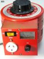
4. The simplest solution that gives the greatest variation for adjusting the power of the amp is a variac to (reduce) the mains voltage to the primary of the power transformer.
- Do not use a Variac to reduce the power of valve amp. Reducing the filament voltage causes cathode poisoning of the output valves.
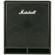
12in guitar speakers have low mass, hi-resonant cones and small voice coils. 2 x 12in speakers provides the minimum radiating area to enable the guitar to have a full bodied sound, at close proximity only.
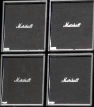
4 x 12in speakers in an open back quad box provides a larger radiating area for the guitar to maintain sounding consistent when performing in a large area. The perfect guitar amp would have 4 quad boxes, 16 x 12in speakers. A large number of speakers provides a large radiating area enabling the guitar strings to be easily modulated by acoustic vibration of the air creating a smoother and more controllable sustain. Also a large radiating area reduces the inverse square law effect, at close proximity, therefore the guitar does not need be loud to obtain good control of acoustic sustain.
The practice of miking or DI a small guitar amp into a PA causes the sound of the guitar to be re-shaped by the sound of the PA.
The above descriptions are generalised principles. The detail within amp circuit designs are variable and complex. Some solid-state amps are inherently unstable and any attempt to apply current drive conversion will cause the amp to oscillate. Some solid-state amps can be easily modified to increase internal stability allowing current drive to be applied. This depends on technical skill and experience of the electronic technician.
Bass guitar
The perfect solid-state bass amp should also have a high output impedance, similar to a valve amp and a guitar amp. No bass amp should be driven into overdrive. The output should never clip into the supply rails. Therefore a bass amp will need much higher voltage supply rails than a guitar amp.
A guitar amp is suited to low voltage supply rails (+30V -30V) to enable the amp to be easily driven into overdrive. A bass amp should have high voltage supply rails (+90V -90V) to avoid any chance of the amp being driven into overdrive. If a bass guitarist periodically requires overdrive to achieve a special effect, then the overdrive sound should be obtained from an effects processor.
Rail supply voltage +90V -90V will enable an output of approx 60V RMS into the speakers at the onset of clipping. 60V RMS into each 15in 8Ω speaker is 450W = 900W total. The transient peak caused by the initial striking of a bass string is approx x10 the average energy. The average energy will be 100W. A small amount of transient clipping is inaudible, therefore the average energy can be as high as 200W before transient clipping becomes objectionable.
At fundamental resonance the impedance of each 8Ω 15in speaker will be approx 32Ω and the impedance will also rise to approx 32Ω above 1kHz. In current drive, the gain of a solid-state amp will increase as the speaker impedance rises, similar to a valve amp. At 32Ω the amp will be capable of approx 200W for 2 x 15in speakers. A solid-state amp with +- 90V rails in current drive will now be able to outperform a 200W valve amp.
 Bass speakers. A conventional solid-state amp (zero output impedance) dampens the natural resonance of a speaker and causes power to decrease as the speaker impedance rises resulting in a flat non-responsive sound that many musicians do not like. Large 15in and 18in speakers tend to sound dead, whereas smaller 10in speakers will sound brighter. Many bass speaker boxes today consist of 4 x 10in speakers that give a bright sound enabling the 2nd harmonic of the bass guitar to be heard clearly. But, unfortunately 10in speakers produce little to zero fundamental. The majority of bands today tend to sound shallow, lacking the deep bass energy that was symbolic of live music in the 60's and 70's.
The problems of amplifying bass-guitar had been inadvertently caused by technical ignorance in not understanding the behaviour (physics) of speakers when driven with conventional solid-state amps. High efficient, large bass speakers similar to the 18in Aura NRT18-8 become ineffective and sound dead when driven with a conventional solid-state amp of zero output impedance (100% damping). However, when these high resonant (high Q) high efficient, large speakers are driven with a valve amp or a solid-state amp in current drive, they spring to life, providing a dynamic transients with a full fundamental energy with bright 2nd harmonic structure of the bass guitar - as the speaker designer intended.
E Q
Guitar amp EQ has been one of the many misunderstood functions guitar amp design. The sound of a guitar amp is primarily shaped by the speakers and the output impedance of the amplifier depending on the amp being valve or conventional solid-state. Most 12in guitar speakers roll off sharply below 100Hz to 150Hz and produce maximum on-axis energy between 2kHz to 4kHz and very little energy above 10kHz. When a guitar amp is driven into overdrive the discordant harmonics above 6kHz are undesirable. The speaker acts as a natural EQ filter.
Tone controls only contribute a subtle function within the overall sound colour formed by the speakers and output impedance of the amp. The most important function of a tone control EQ system is to be able to bypass it. When given the opportunity many bass guitarists prefer the sound of their bass guitar with no EQ. But, very few guitar and bass amps provide a switch for allowing the EQ tone controls to be bypassed and therefore many if not most musicians have never had the opportunity to hear their instrument without the colouration of the tone controls being imposed on their sound.
Does a perfect EG for a guitar and bass amp exist?
When playing a steel string solid body guitar or bass through a typical HiFi speaker system the sound appears to be muggy, as though a blanket has been placed over the instrument. This is due to a combination of factors that include how magnetic pickups function and where the pickups are placed. As a generalisation, the fundamental frequency of the notes will be approx even in energy. The 2nd harmonic structure of the notes is often higher in energy than the fundamentals, but the harmonic structure decreases at -3dB to -6dB per octave. A musical note is a combination of its fundamental and its harmonic energy. When many notes are being played (chord) the harmonic interaction becomes infinitely complex.
As an analogy, a musical instrument behaves similar to a pink noise generator, delivering equal energy per octave, that is, if every note (frequency) was played at the same time. This is impossible to demonstrate with a guitar or bass, but can be easily demonstrated with a keyboard by simply pressing down on all the keys at the same time. Because the total number of frequencies doubles in each octave increase, the energy of each individual note will appear to decrease by 1/2 in each upper octave. A880 will appear to be 1/2 the energy of A440 and A440 will appear to be 1/2 the energy of A220 etc. We must remember that this explanation is a generalised analogy of an extremely complex interactive system.
3dB/octave. For a musical instrument to sound correct, each note has to appear to deliver comparatively equal energy with all the other notes. Therefore, the frequency response of an instrument amp (guitar and bass) must be rotated approx 3dB/octave for all the notes to appear to have equal energy. This 3dB/octave is the basic reference for the instrument to have an equal energy response for each note being played. &It is only from this +3dB/octave reference that EQ tone controls will appear to function correctly to further boost or reduce the frequency response of the instrument in a way that sounds congruent and easily managed. EQ shelving is capable of giving a consistent rise or fall (dB/octave) across a broad frequency range.
www.mixinglessons.com/shelving-filter
An excellent explanation of the energy response of guitar pickups by Don Tillman is available on his site, Guitar Electronics www.till.com / articles
Closing note. Some EQ tone control designs are very clever, but there rarely appears to be any consistency in how tone control EQ design evolved. When looking at the circuits of many guitar amps it appears that this basic understanding of the physics of 3dB/octave does not appear to be understood or acted upon. Guitar and bass amps appear to have evolved in a hotch-potch, trial and error approach. Many designs are copied from what ever amp attained the highest celebrity status. The design of tone controls appears to have evolved from an intuitive sense without fully understanding the underlying physics, plus what may have been smoked at the time.