

Class D amplifiers are described as pulse width modulation (PWM) amplifiers. Class D is similar to a switch mode power supply. Switch mode power supplies and Class D amplifiers are low mass, generate very little heat and approx 90% efficient. The majority of small amplifiers less that 20W in computers and domestic application including TVs etc are now Class D amplifiers. Above 20W the complexity and problems of Class D increase exponentially. Similar to switch mode power supplies, Class D amplifiers are virtually un-serviceable and life after 7 years considered a blessing.
Switching on and off a light bulb, electric motor, electric heater etc at high speed to control power is not rocket science to understand. With a little imagination a speaker could be switched on and off across 2 batteries and by varying the on time compared to the off time (providing the switching speed is above hearing range) the mass of the cone will average the energy to represent an audio signal.
Pre 1970 valve/tube technology reigned supreme. Outside of experimental computers the first transistors were used in small cheap radios which is how the Japanese electronics industry and Sony began. Transistors do and not have a linear function similar to valves, but are ideally suited to switching on and off. Class B analogue transistor amplifiers above 10W were originally unreliable. It was assumed that transistors would not be suited for making high powered class AB amplifiers.
In 1964 Clive Sinclair, an electronic inventive genius, along with fellow engineer Gordon Edge, developed the first PWM amplifier. The X-10 was marketed as 10W but only produced 2 to 3W. The Z-12 arrived shortly later which reliably produced 12W, and the race was on. Almost every young electronic audio enthusiast started experimenting with PWM amplifiers. It was believed that PWM amplifiers capable of 100s of watts would be available at low cost before a man would set foot on the moon.
www.nvg.org/ Planet Sinclair
wikipedia.org/ Clive Sinclair
Similar to Dr Frankenstein everyone was originally unaware of the monstrous lurking problems that were about to be unleashed. Any radio or TV in close vicinity to a PWM amplifier was blocked out by the Rf noise interference generated by the high frequency switching of the transistors. Test equipment capable of analysing switching frequency rise times that approached the limits of physics was not readily available. Government communication authorities quickly outlawed the use of any device that interfered with Rf transmissions. Another 30 years would pass before the science for controlling PWM Rf noise radiation was better understood. Very few high power PWM amplifiers today are CE certified Communication emission
Understanding how a PWM amplifier works requires a lateral shift in thinking, &but once the basic principle is seen it appears almost obvious. PWM does not require separate switching for each half of the wave form as in the first pic. A fixed high frequency square wave 100kHz to 1MHz is width modulated by the audio sine wave. At the output is a filter stopping everything above 20kHz from getting to the speaker.
The above pic is expanded to show only 16 pulses across an audio sine wave. When the square pulse widths are equal the averaged energy output is zero. As the pulse widths become wider than equal the averaged energy shifts toward the +Ve half of the audio sine wave. As the pulse widths become less than equal the averaged energy shifts toward -Ve half of the audio sine wave. But how is this achieved?
(1) To make the transition from a audio sine wave to a fixed 100kHz to 1MHz modulated square wave that simulates the energy of the sine wave, requires an intermediate step. First, a fixed 100kHz to 1MHz triangle wave is generated. The triangular wave must be approx x 100 the highest audio frequency. As the sine wave moves across the high frequency triangle wave a comparator recognises which part of the sine wave is above or below the points crossed on the triangle wave.
(2) As the triangle wave is crossed by the sine wave the MOS-FETs are turned on or off generating a high energy square wave of varying width. The MOS-FETs are not capable of turning on and off instantly. In the real world the speed of light is a theoretical concept. The slew of the MOS-FETs governs how quickly the change from off to on and off again can happen.
(3) This transition from off to on represents the leading or trailing edge of an extreme high frequency which is magnitudes higher than the 100KHz to 1MHz fixed switching frequency. As the corners of the leading and trailing edges of the square wave make the transition from vertical to horizontal Rf ringing noise is generated. This Rf ringing also creates secondary problems inside the MOS-FETs that result in excessive heating and potential breakdowns.
The lower part of the above pic shows a more realistic view of the hi frequency square wave in comparison the comparatively low frequency audio sine wave. It clearly shows the noise of the switching frequency imposed on the audio sine wave that has to be filtered out. The high frequency modulating frequency has to be filtered out leaving the resultant energy of the amplified audio. The LPF Low pass filter only allows everything below 20kHz to get to the speaker.
Class D amplifiers are similar to the switch mode power supplies in computers and therefore non user serviceable. Failures are simply dealt with by warranty replacement or purchasing a new amplifier. The technology of professional high power Class D amplifiers is so complex and fragile that reliable operation of after 7 years should not be expected.
A deeper technical understanding of PWM amplifiers and their limitations is on this PDF published by component manufacturer IR (International Rectifier)
Application Note AN-1071
by Jun Honda and Jonathan Adams
sound-au.com PWM An excellent technical review of PWM problems and solutions.
Class D Audio Amplifiers: What, Why, and How
wikipedia.org/ Class D amplifier
Switch mode power supply
Many household white goods, refrigerators, steam irons and electric ovens are simply controlled by being switched on and off. As the refrigerators warms up it is switched on until it cools down, then it is switched off again and so on. Electric ovens and steam irons function in reverse way. The time it is switched on compared to the time it is switched on is the duty cycle. Duty cycle is measured as % of on time compared to off time. A refrigerator with a permanently open door would have a duty cycle of 100%. With the door closed the duty cycle may be only 10% depending on the quality of insulation. A refrigerator may be on for 5 minutes and off for 50 minutes and so on to maintain cold temperature. The longer the time span (clock speed) of the duty cycle the greater will be the temperature difference between on and off. The fastest time a refrigerator may be able to turn on and off would be approx 1 minute. Therefore, it would have a clock speed of 1 minute. If the refrigerator had a higher clock speed of 1 second (1Hz) so it could be turned on for 1 second and off for 10 seconds maintaining the same duty cycle of 10% the temperature would be controlled more evenly.
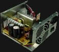
With a conventional 'capacitor input' power supply the mains frequency of 50Hz or 60Hz can be described as the clock speed. A 50Hz or 60Hz clock speed is very slow and the reason for the large ripple in the supply rails. If the mains frequency was 1kHz then the ripple on the supply rails would be virtually non existent. Switch mode power supplies in computers and most home entertainment systems DVDs and plug packs etc have clock speeds of 25kHz to 100kHz. A computer switch mode power supply does not use a large heavy mains transformer. The advantage of a switch mode power supply is reduced mass, but its circuitry is extremely complex and virtually un-serviceable.
The mains voltage is fed into through an electro magnetic interference (EMI) filter into a bridge or voltage doubler (VD) rectifier and converted directly to DC. Most switch mode supplies are internally designed to function between 280V DC to 340V DC.
240V AC mains x 1.414 = 340V DC with bridge rectification.
110V AC mains x 1.414 x 2 = 310V DC with voltage doubler rectification.
The EMI filter stops Rf (radio frequency) switching noise generated by the switch mode power supply from getting back out into the 110V 240V mains system effecting other equipment connected to the mains. There are strict international regulations governing the maximum Rf radio frequency noise that electronic products must comply within. This regulation is named C-tic.
(1) The mains rectified 300V DC approx is switched on and off through a transformer. The MOS-FET act as a switch. The switching speed can be between 25kHz and 100kHz. The PWM (pulse width modulator) controls the duty cycle of the switching frequency which is similar to a square wave that has variable width. The transformer is specifically designed for switching frequencies of approx 50kHz. High frequency transformers are very small and therefore have little mass.
(2) The secondary of the transformer reduces the switched AC pulses to a lower voltage, plus isolating the mains to ensure electrical safety. The diode then converts the secondary pulses to the required polarity. The secondary electrolytic capacitor smooths out the 50kHz DC pulses to an almost perfectly smooth DC supply.
(3) The secondary voltage is fed back into a comparator within the PWM. The PWM then automatically adjusts the width (duty cycle) of the turn on and off pulses to the power MOS-FET which acts as the high frequency switch, controlling the current (A) through the primary of the high frequency transformer, which in turn corrects the voltage at the secondary to insure that the output DC voltage is exact.
The high switching frequency gives the switch mode power supply a unique advantage of providing a near perfect ripple free smooth and regulated DC supply voltage that does not decrease in voltage as extra current is required.
However, switch mode power supplies are extremely complex. The high switching frequency technology is in the Rf radio frequency band. This causes major headaches to technically manage containing Rf radiation from the printed circuit tracks and connecting wires within the circuit getting to the outside world and causing Rf noise contamination in radio and TV. Also, the circuit operation is extremely fragile and if any fault occurs (no matter how small) it contaminates almost every sector of the circuit.
Switch mode power supplies are non user serviceable, failures are simply dealt with by trashing the power supply and purchasing a new one. Attempting to service a switch mode power supply is virtually out of the question, except for fanatics who have infinite time. The technology is so complex and fragile that reliable operation after 7 years is not always expected but considered a blessing. As the world converts to using switch mode power supplies and PWM Class D audio amplifiers, they will eventually end up as the dominant mass of rubbish land fills.