

A small input line level signal 100mV to 1V is amplified by the op-amp driver circuit. A correctly designed driver circuit is capable of amplifying the signal (perfectly) to the exact height of the + - V rail supply. Op-amp driver circuits are not capable of driving a speaker directly because it can not provide sufficient current (amperes) 10mA approx. Output transistors do not increase the size of the signal but simply add current (amperes) 100:1 approx to drive the speaker. The bias string eliminates the crossover gap as previously described.
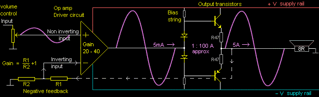
The driver circuit is described as a high voltage op-amp (operational amplifier). Op-amps are drawn as a triangle with 2 inputs. The inputs are described as non-inverting with a + symbol and inverting with a - symbol. The input signal goes to the non-inverting + input. The output of the amplifier is feed back to the - inverting input, described as negative feedback.
Gain. The voltage gain of an op-amp can be adjusted by resistors R1 and R2. Op-amp gain = R1/R2 +1. Power amplifier gains will typically be between 20:1 and 40:1. There is no international standard for the set gain of amplifiers. In domestic system amplifiers the loudness level is simply adjusted with the volume control. In large sound re-enforcement installations many amplifiers are placed in racks. Not to have an international agreed 'gain standard' for professional amplifiers is irresponsible and a nightmare to manage.
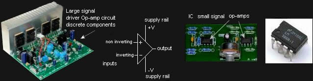
Large driver op-amps for power amplifiers are mostly made from discrete (separate) components and designed specifically for each application. IC (integrated circuit) small signal op-amps are used in almost all audio pre-amplifiers and signal processing equipment. Small signal IC op-amps are designed to be powered from + - 15V supply rails, or less. IC op-amps are available from many suppliers. High-precision ultra low noise op-amps are understandably more expensive and are designed for instrumentation measurement. The average low cost IC op-amp is used for general domestic audio equipment. The basic operational principle and internal circuit of all op-amps is similar and their performance attains to what is described as 'the perfect amplifier'.
The perfect operational amplifier would aspire to have infinite attributes. Infinity does not exist (universe excepted) but the ability to approach infinity does. 'Asymptotic' is a technical term that means approaching infinity.
- Infinite power
- Infinite gain
- Infinite bandwidth
- Infinite high input impedance
- Infinite low output impedance
- Infinite low distortion
- Infinite low noise
(1) Infinite power is unrealistic but high-powered amplifiers are available with more power than is required, therefore power is not a limitation. In a past era when only valve/tube amps existed, power was a limitation.
(2) Infinite gain is not necessary for any known audio application. The maximum gain normally required may be 100. Cheap op-amps are capable of a gain of 1 million. Special op-amps can be much higher.
(3) Infinite bandwidth is also unnecessary as the audio spectrum is from 20Hz to 20KHz. The cheapest op-amp is capable of 1MHz. Special op-amps can go higher than 100MHz.
(4) Infinite high input impedance. In normal audio applications an input impedance of 1M Ohm is sometimes required. Special op-amps can easily achieve 100M Ohm and higher.
(5) Infinite low output impedance is achievable but rarely required. It is possible to make an op-amp circuit achieve negative output impedance.
(6) Infinite low distortion. Cheap op-amps achieve distortion figures magnitudes below what is audibly detectable, and special op-amps achieve low distortion figures at the threshold of what is measurable.
(7) Infinite low noise. The lowest noise is thermionic electron noise of components limited by the laws of physics. There are precision low noise op-amps available that approach this threshold.
The op-amp miracle
Modern electronics and ICs are possibly the closest thing we can describe as being miraculous. The following description of op-amps is an overview and appreciation of how with a few simple components a beautifully complex circuit can function.
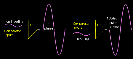
An op-amp has 2 inputs described as a comparator. One non-inverting input (+ symbol) and one inverting input (- symbol). An op-amp has almost infinite gain by comparison to what is required.
When a signal is put into the + non-inverting input the output will be in phase with the input and amplified toward infinity. When a signal is put into the - inverting input the output will be 180deg out of phase with the input and amplified toward infinity.
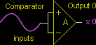
The gain of the op-amp responds to the difference between the 2 inputs which is described as a comparator. In the right pic Op-amp A has both inputs joined together. The joined non-inverting and inverting inputs cancel each other, therefore no output.
In op-amp B the output is directly fed back (100% feedback) to the -inverting input which results in the same signal on both comparator inputs. This is like trying to describe which comes first (chicken or egg) at the speed of light. At the moment a signal appears at the input the output will attempt to have infinite gain. But, the moment the signal at the inverting input is at the same size as the incoming signal on the + non-inverting input, the op-amp ceases to have any further gain.
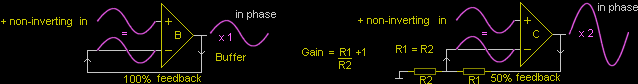
Op-amp C has two resistors in series to ground. & The junction of the resistors is a voltage divider which is connected to the -inverting input. Because both resistors are the same value, the voltage at the junction will be 1/2. Therefore, the amplified output signal will have to be x2 before the signal at both inputs will be the same, causing the op-amp to have no further gain.
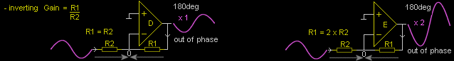
Op-amps D and E have the input signal fed to the -inverting input. The output will be 180deg out of phase with the input. The output is also fed back (feedback) to the -inverting input via R1. The moment the fed back amplified output signal is the same size as the incoming input signal via R2, they will both cancel each other out, causing both inputs to be the same and thereby causing the gain of the op-amp to cease amplifying the signal any further. The gain is adjusted by simply changing the values of R1 and R2.
A simple principle taught to electronic students about op-amps. "In a circuit, an op-amp will attempt to make both inputs have the same voltage. If not, the output will take the sign of whichever input is most +ve".
Inside the op-amp
An op-amp can be constructed with 3 small 10 cent signal transistors and three 2k2 resistors. However, most IC op-amps have 30 to 100 internal transistors. The below pic is a simple circuit that will actually work and is an ideal beginning for electronic students to construct and experiment with to obtain an understanding of the basic principles. The below circuit will work on any voltage between 5 to 30V.
The first 2 NPN transistors with their emitters joined together (long tail pair) is described as a differential input. The 3rd PNP transistor is described as a Class A driver, which means that the emitter is connected to the +V rail supply and the collector is the output. The output voltage is the result of a difference between the two inputs. A very small difference voltage between the two inputs of micro Volts will cause the output to flip to the +V rail or to -V rail. An op-amp used to switch between the rails is described as a comparator.
The same circuit can be constructed with complement NPN for PNP transistors and +V -V rails reversed.
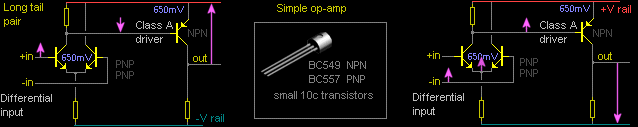
Comparator. A small +V on the +non-inverting input (compared to the -inverting input) will cause the first transistor to conduct. The voltage at the collector will drop toward the -V rail. This will turn on the NPN Class A driver causing the collector (output) to flip to the +V rail. Vice-versa for a small -V on the +non-inverting input.
A small +V at the -inverting input (compared to the + non-inverting input) will cause the emitter second transistor of the differential pair to follow its base within 650mV. Because both emitters are joined this will cause the emitter of the first transistor to decrease below the 650mV threshold which will turn off the first +non-inverting transistor (open circuit), causing the voltage at the collector to go directly to the +V rail. This will turn off the Class A driver (open circuit) as a switch causing the collector (output) to drop to the -V rail. Vice-versa for a small -V on the -inverting input.
Linear audio. The output can be connected directly to the -inverting input, or through R1 R2 to provide gain. A small +V on the +non-inverting input (compared to the -inverting input) will cause the first transistor to conduct. The voltage at the collector will drop toward the -V rail. This will turn on the NPN Class A driver causing the collector (output) to attempt to flip to the +V rail. But, the output is feed back to the base of the -inverting input transistor. The emitters of the differential pair are joined together. Therefore, what happens on the emitter of the -inverting input also happens on the emitter of the +non-inverting input. Both base and emitters are locked together within 650mV.
The emitter of the +non-inverting input is influenced from the output attempting to cause the 650mV difference between base and emitter to be reduced or negated therefore counteracting the effect of the incoming signal. This counteracting effect of the feedback causes the output to follow the input directly. Only by reducing the amount of feedback through R1 R2 can the output have gain.
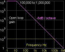
Open loop gain is the maximum gain of the op-amp without negative feedback and is specified at DC. From approx 10Hz the open loop gain will decrease at 6dB / octave as a result of slew. At 10kHz most op-amps in audio circuits will have a gain of approx 1,000 and at 1MHz will have unity gain. The right pic shows an average $1 op-amp is capable of a flat response to 100kHz with a gain of 100. The maximum signal gain required for audio application with negative feedback is often less than 100.
Common mode rejection. Absolutely no variations on the supply rails can effect the audio signal. The op-amp output can only respond to the signal between the inputs and not to any variation on the supply rails. Nothing else whatsoever can effect what happens at the output.
Current source. Op-amp performance is greatly enhanced by a constant current source from the -V rail to the differential inputs and Class A driver. The constant current source insures that the current through the differential inputs and the Class A driver remains absolutely constant regardless of any changes in the supply rails. This enables the op-amp to perform perfectly from any voltage between 5V to 30V. The constant current source absolutely insures that supply rail noise and ripple can not in any way effect the audio signal.
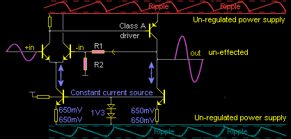
A simple constant current source consists of transistor with its base locked by small fixed reference voltage. The 1V3 (650mV + 650mV) of two diodes acts as a fixed reference. There is 650mV between the Base and emitter of a transistor and therefor another 650mV must be across the resistor between the emitter and the -V rail. The fixed 650mV across the resistor insures a fixed reference current through the resistor which is also the fixed current through the transistor. Some constant current source circuits can be more complex.
wikipedia.org / Op-amp
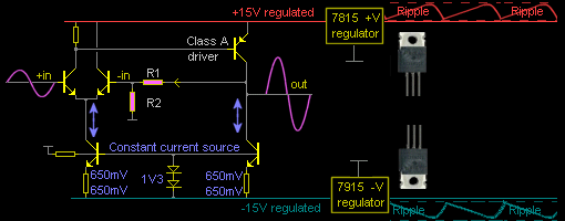
7815 Voltage regulators. All quality audio pre-amplifiers and signal processors have power supplies with additional voltage regulators that provide a smooth ripple free + - 15V rail supply to all op-amps. Special low voltage op-amps in iPhones (etc) are not discussed in this text. The specified + - 15V rails allows the correct line level with sufficient dynamic range without the signal being clipped into the rails.
Some audiophiles are being conned by dishonest audio technicians claiming that auditory fidelity in pre-amplifiers and CD players can be improved if the 7815/7915 voltage regulators are replaced by a special audiophile brand at high cost $x$. The only audio requirement for ultra low noise voltage regulators and op-amps is in phantom power supplies for low noise microphones pre-amplifier circuits, and phono pre-amps for transformer-less moving coil magnetic cartridges.