

Root mean square (RMS). A sine wave is similar to an audio wave that constantly changes from 0 to maximum. This is similar to driving a vehicle and constantly stopping at red lights. Therefore, the peak speed of the vehicle has to be greater than another vehicle that is not stopping at lights, travelling the same distance in the same time. RMS is the AC (alternating current) equivalent to DC (direct current) as resultant power to generate the same amount of heat. The exact formula is based on the square root of 2, √2 = 1.414 or 1/√2 = 0.707.
Resistance (R) is the same as Ω Ohms (constant over frequency). Impedance is resistance that changes with frequency. A speaker voice coil changes resistance with frequency, 8 Ohm or 4 Ohm measured at 400 Hz.
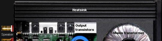
The large output transistors are bolted to a heat sink. The output transistors provide current from the voltage supply rails to drive the speaker. Output transistors do not increase the size of the music signal. The maximum power available to drive the speaker is dependant on the voltage and current from the supply rails. The average high-power professional amplifier will have + - 75V rails. Rarely do supply rails exceed + - 100V.
The modern marketing trend with many domestic amplifiers is to state power output figures that have no technical meaning. A small 3W computer speaker with an internal amplifier can be marketed as 1,000W. Only by testing, or looking at a circuit diagram, is it possible to know the actual power capacity of an amplifier.
The supply rails in an average 50W per channel domestic amplifier will be approx 30V. There are 2 supply rails +30V and -30V. This is correctly stated as + - 30V. The difference between the supply rails is 60V. The speaker is connected by one transistor to one supply rail at a time. The maximum voltage to the speaker can be no greater than 30V. That is +30V or -30V at any one point in time.
The peak of the sine wave is always slightly less than the rail voltage, but we will begin with peak of the sine wave as being the same as the rail voltage. Because a sine wave is constantly changing, (between zero and maximum) the RMS voltage, or power over 1 second, has to be calculated. This is calculated from measuring the peak of the sine wave. Peak 30V x 0.707 = 21.21V RMS (20V RMS approx with losses).
Power watts can be directly calculated from the output RMS voltage and the speaker R as V²/R. Speaker 8R resistance, 8Ω Ohms. 20V x 20V / 8R = 50W.
Clipping. .If the audio signal is driven into the rail supply then the speaker is held at 30V for a longer period of time. The more the sine wave is driven into clipping the more it will change shape toward a square wave. The RMS formula (peak V x 0.707), for a sine wave no longer applies because the voltage into the speaker will remain at 30V, flipping directly between +30V or -30V, dependant of frequency. 30V x 30V / 8R = 112W (100W approx). We can now see that power to the speaker can be doubled by simply driving the amplifier into extreme clipping or overload. Many guitar players drive their amps in clipped distortion 100% of the time. Guitar amplifiers have multi-stage high gain pre-amplifiers to enable the output to be easily driven into clipping. The distorted guitar sound now remains at a constant level, and is described as 'sustain'.
Heat dissipation. Many amplifiers have insufficient heat sink or fan cooling. This may happen because of incorrect calculations, but is mostly the result of heat sink being too expensive. Almost all output transistors are destroyed by overheating. Heat is the enemy of transistors. No solid-state amplifier needs to be warmed up. The colder they are the better they will perform and the more reliable they will be. Many Audiophiles believe amplifiers sound magical when warm. Science has no meaning to fanatical believers.
The above pic is a simplified example, showing transistor heat generated in one half of the sine wave. The resistance between collector and emitter changes from an open circuit to a short circuit. &At the half way point, (at one moment in time) the resistance between collector and emitter equals the resistance of the speaker. Therefore, 28W is dissipated in the speaker and 28W is dissipated in the transistor (at one moment in time). When the sine wave has reached the 30V rail, the transistor is now a short circuit. Similar to an off on switch in the closed position, therefore no heat is dissipated across the transistor.
At the half point maximum heat is dissipated by the transistor. At full power less heat is dissipated by the transistor. When the amplifier is driven hard into clipping, very little heat is dissipated by the transistor. However, this calculation is simplified to instantaneous points in time to give easy examples. Real RMS calculations are taken over 1 second and require the Ohms law formula.
Amplifier efficiency. With Ohms law we can calculate the RMS power into the speaker. Then we can calculate how much power is taken from the power supply. The difference between the power to the speaker and the power from the rail supply is the power lost in the heat sink. The below description shows 2 x 8R speakers in parallel = 4R. 50W into each 8R speaker, is the same as 100W into a single 4R speaker, and 4R is used in this description to give 100W. Using 100W as full power is easier to describe % efficiency.
20V RMS is the maximum level before the peak of the sine wave clips the 30V supply. 20/4R = 5A of current into the speaker. 20V x 5A = 100W. The 5A is supplied from the 30V supply (through the transistor) to the 4R speaker. 5A x 30V = 150W. 50W heat is dissipated by the transistor into the heat sink. Therefore, at full power the amplifier is approx 65% to 70% efficient.
70% efficient. Class B solid-state amplifiers are described as being 70% efficient at full power. In academic text the peak of a 20V RMS sine wave is 28V (not 30V), (5A x 28V = 140W) which results in a 70% efficiency calculation. It is not possible for output transistors to reduce to absolute 0R, at the peak of the sine wave enabling the speaker to reach the 30V rail. There is a small residual on resistance in the output transistor at the peak of the sine wave. The peak of the sine wave can only get to within approx 2V to 6V of the 30V supply rail. This limitation results in another 4% approx loss. &At lower power the efficiency decreases. At 1/2 power the amplifier is approx 50% efficient, at 1/4 power the amplifier is approx 30% efficient.
The graph on the right shows heat dissipated into the heat-sink from the output transistors remains (approx) constant between 1/4 power to full power. Maximum heat is created at approx 1/2 power.
The % efficiency between power to the speaker and power lost as heat in the transistor, changes between 50% to 70%. However, the most important thing to understand is; heat delivered into the heat sink by the output transistors remains approx constant between 1/4 power to full power. sound-au.com/amp-efficiency
Whatever the full power rating of an amplifier is, approx 1/3 of that power figure is converted into heat by the output transistors. This 1/3 of the full power figure as heat into the heat sink remains approx constant between 1/4 power to full power. Only when the power to the speaker is reduced below 1/4 of full power does the heat delivered to the heat sink start to reduce.
Why do some amps sound better when warm?
If there is a verifiable audible difference between hot and cold in an amplifier then there is a fault condition which may or may not effect the reliability of the amplifier. This could be because of a circuit design fault, a component fault, or a connection fault. Also, the internal parameters of all solid-state devices (transistors and FETs) change with temperature. A common example is the quiescent bias current through the output transistors which often increases when the operating temperature increases.
A small bias servo transistor is sometimes bolted to the heat sink between the output transistors as shown in the above left pic. In many amplifiers the heat sink is too small and the temperature may rise to 20deg to 40deg above ambient before there is sufficient thermal difference to the surrounding air to achieve stable dissipation. The bias servo transistor may be calibrated to provide the correct quiescent current through the output transistors (to insure there is zero crossover distortion) only when the heat sink temperature has risen to an unfortunately higher but stable level. These problems can also be the result of manufacturing cost cutting, where the extra profits can be used to market the benefit of an amplifier that must be warmed up before it will perform correctly.
Speaker load and power output
In a capitalistic society, writing large numbers in front of watts in marketing brochures results in larger profits. Amplifiers can be marketed as 1,000W, or 1,000,000W The real output power (watts) of an amplifier is the result of the maximum voltage and amperes available from the supply rails and the speaker impedance (R). The reliability of an amplifier is mostly dependant the quality and number of output transistors, power supply regulation and size of heat sink. Increasing the number of output transistors distributes the current (amperes) between them and provides better thermal dissipation into the heat sink.
An amplifier marketed as 200W may or may not be able to deliver 200W into a 8R speaker. It may be only able to deliver 50W into a single 8R speaker. However, it may be able to deliver 200W into 2R, which is the same as 4 x 8R speakers in parallel = 2R.
With a + - 30V rail supply the maximum output is 20V RMS. The on resistance of output transistors limits how close the peak of the sine wave can get to the 30V rail supply. The below pic shows a 2V difference. In many amplifiers the difference V between the peak of the audio wave and the V supply rail can be much greater. The below example assumes a + - 30V rail supply that does not change between 0 power to full power.
There is limit to how much current (A) 1 pair of output transistors can conduct and dissipate heat into a heat sink. Paralleling 2 x 8R speakers = 4R and may overheat 1 pair of output transistors and cause them to fail. If an amplifier is to drive a 4R or 2R load by paralleling many 8R speakers, then it is essential to parallel more output transistors to provide more current (A), therefore dissipating more heat into the heat sink. Also, the heat sink will have to be larger.
1 x 8R speaker = 8R 20V RMS x 2.5A = 50W
2 x 8R speakers = 4R 20V RMS x 5A = 100W
3 x 8R speakers = 2.6R 20V RMS x 7.5A = 150W
4 x 8R speakers = 2R 20V RMS x 10A = 200W
In an imaginary perfect amplifier the + - V supply rail would remain constant (under load) at full power. The on resistance of the output transistors would be 0R and the peak of the sine wave which would reach the + - V supply rail. In a real amplifier the supply rails would be approx + - 35V at 0 Power (0 load), and collapse to + - 30V at full power (under load). This is described as 'power supply deregulation'. Therefore, it is essential to measure the + - V supply rails at full power (under load) to calculate maximum power.
45V RMS into 8R = 250W. The peak of a 45V RMS sine wave is 64V. A typical amplifier with + - 75V rail supply will collapse to approx + - 67V (with an 8R load). With 2 8R speakers in parallel (4R) the + - 75V rail supply will collapse down to + - 62V. Because of the higher current (A) the transistor on resistance will now have a greater voltage across it (approx 6V) causing the peak of the sine wave to be reduced to 56V. Total power into 4R is 400W. Therefore, power to each 8R speaker is now 200W.