

Equalisation (EQ). The primary use of EQ is shelving. Shelving filters unwanted frequencies from being amplified or recorded, e.g. stopping bass frequencies and popping being amplified from vocal microphones. The secondary use for EQ is tonal colouring and presence. Presence (approx 2k Hz) can cause an instrument or voice to have the feeling of being positioned forward or back.
For live productions, avoid at all costs the use of graphic parametric and Q controls in extreme boost positions. This increases the gain of the centre frequency, often causing acoustic ringing and instant mic feedback. It is possible to use high Q in cut positions to control mic feedback problems. A false belief is that EQ Q in cut positions can reduce room reverberation or compensate for peaks in poor quality speaker systems. This has no more effect than simply reducing the level.
Q is a ratio number referring to Quality of resonance. Filter networks in graphic and parametric equalisers cut or boost a given centre frequency pushing it toward resonance. If the Q is boosted too high, music information that coincides with the centre frequency will ring. This ringing reflects complex harmonics on both sides of the centre frequency. Also, the slopes of the filter rotate phase in opposite directions. Applying Q to a narrow band of frequencies creates distortion, but if applied subtly, can have a pleasing effect for managing specific instruments.
To improve clarity and presence, the best practice is to use shelving and minimal slopes over a broad range as shown in the pic below, especially for live productions. However, primary EQ management is best applied with appropriate microphone technique.
Slopes are most effective for rotating the frequency response over a broad range at a gentle angle (3dB / octave), over 1 decade (ratio 1:10). This broad EQ management achieves overall brightness and closeness for voice and voice range instruments with zero distortion or ringing, and maintains full fidelity. The above pic shows a useful example between 300Hz and 3KHz. Above and below the knee frequencies, the response is returned to flat. This is essential to enable frequencies below 300Hz to be heard and to stop frequencies above 3KHz from being unnecessarily boosted. This rotation angle can also be reversed to reduce harshness or obtain a softer feel to the voice and voice instruments.
Spectral energy. The average spectral energy of music is flat between 100Hz and 1kHz. Music has approx equal energy on either side of middle C or 300Hz. The highest musical notes are approx 2KHz. Above 1KHz the harmonics decrease in energy at approx -6dB / octave.
Above 2kHz music energy is approx -6dB (1/4).
Above 4kHz music energy is approx -12dB (1/16).
Above 10kHz music energy is approx -20dB (1/100).
This is the reason sound systems need greater power for bass speakers, but less power for tweeters.
Delay
Delay has a multitude of uses for recording, giving a feeling of thickening to a voice or instrument. A voice or instrument as mono in both channels, left and right, with one channel delayed, causes an illusion of left or right bias positioning, separate from listening position. This delay effect can also be enhanced with a stereo mic.
Repetitive diminishing delay is heard as reverb and echo, which is pleasing when used subtly, but reverb and echo reduce intelligibility and forces an association of distance. Introducing a space between the original sound and the reverberation limits the reverberation from reducing intelligibility. For live productions, adding reverb or echo often exaggerates problems in an already overly reverberant room (echo is delay, heard as distinct repeat).
Compression-limiting
When skilfully used, compression can allow subtle sounds to be heard while louder sounds are kept under control. A whisper and a scream can be kept at the same level. Also, live production can benefit with peak limiting to avoid the sound system from being driven into distortion.
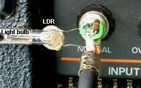
The above pic is the simplest limiter that can be made. An LDR (light dependant resistor) is connected across the input pin of the jack plug to earth. A small 12V light bulb is connected across the speaker output. As the light bulb lights up with the music, the LDR resistance decreases and partially shorts out the signal. This simple 2 component circuit works so well that some valve compressor limiters actually use variations of this circuit (with a few more components).
By paying attention to the graph above, compression can be viewed as the high levels above 0VU being compressed to a lower level, or the low levels below 0VU being increased to a higher level. The result is the same, everything gets squashed together. This example shows the compressor set to 2:1 ratio. Peak-limiting can be adjusted to any level and changed in ratio and used with or without continuous compression.
Many compressor limiters also include noise gates. A noise gate turns off the input at very low signal levels so not to hear noise hiss from the mixer circuit or the background studio noise picked up by the microphones. Noise gates are also used with guitar players that have very noisy valve guitar amps that hum and buzz continuously.
Ducking or cross-limiting. Complex compression techniques are used for TV and film when the main dialogue is used to compress the background music. The dialogue causes the background music to reduce (duck below) enabling speech articulation to be retained. The dialogue automatically acts on and compresses the music and background effects in real time. The overall level remains the same. This is heard on talk back radio, when the announcer talks over the caller.
Peak-limiting is essential to avoid peak transients from clipping. Most analogue mixing consoles have a internal supply voltage of +-15V = 30V P/P which will allow a maximum signal of 7V to 10V RMS 20dBm approx. Traditional practices of mixing states that music signals must not be greater than -6dB from the maximum voltage limit where rail clipping occurs. This is referred to as 6dB headroom. Allowing for the 6dB headroom, and a maximum 20dB transient capacity, the average analogue mixing console, depending on noise floor, has difficulty in obtaining a 60dB dynamic range.
Transients can be much greater than 20dB ratio 1:10 above than average music level. Applying peak limiting to control transients to within 20dB of the average music level has almost zero audible effect on the music however, limiting transients to lower levels within 10dB may have a noticeable effect.
The time it takes for peak limiting to compress and release, it should not interfere with the waveform cycle. This is a compromise as seen in the above pic. Acting too fast will distort the low frequencies causing excessive non-symmetry in the waveform, resulting in 2nd harmonic distortion. Too slow -- and the first few high frequency transients get through. When the loud passage ends, the release delay time can cause the music signal to be reduced in level or at worst, momentarily reduced to zero. Excessive peak limiting and compression creates distortion and therefore should be used with subtlety and skill.
The above pic shows excessive compression-limiting in steps. Peak-limiting is used to reduce the transients to almost zero. Compression then reduces the dynamic range by squashing the music, reducing the upper level and increasing the lower level, then the compressed music is turned up in gain to the maximum headroom level. At this maximum level, with almost zero dynamic range and with all the transients, nuance, harmonics, and detail removed, along with removed stereo depth of field, the sound is at one mono-tonous LOUD level.
Compression madness. Commercial marketing drives the worst of this behaviour. Radio and TV broadcasting is restricted within a limited dynamic range. The aim is to make the pop music or commercial appear to be louder by compressing the music. This enables the average level to be artificially increased. The next trick is to add aural exciters which distort the harmonics within the music, similar to fingernails on an old school chalk black board. There are many variations in how this is done.
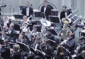
The above left pic represents a live orchestra. The above right pic represents the recorded over-compressed orchestra. Small sounds are brought up up ↑ ↑ ↑ and louder instruments are pushed down down ↓ ↓ ↓. The dynamic power of the orchestra is compressed so all instruments are at the same level. Everything can now be heard on small studio monitors and small domestic sound systems. The compressed sound gives an illusion of the full orchestra - but this is illusion. The compressed orchestra is highly inter-modulated and distorted. Small low fidelity speakers mask this distortion.

When an over-compressed recording is played back on a large full-fidelity active sound system, the inter-modulation and distortion caused by excessive compression is now revealed. Intolerable to listen to, flat and lifeless, the instruments no longer sound natural, no nuance, no stereo imaging and no depth of field remain.
Best practice is to apply compression-limiting to individual voices and instruments s-e-p-a-r-a-t-e-l-y. Applying compression-limiting to a completed mix causes the instruments and voices to inter-modulate with each other. Worst of all is applying compression limiting to a compiled stereo mix. The (left/bar) - (right/bar) out of phase components are exaggerated, resulting in loss of stereo image and depth of field. Exaggerated examples of this are radio, TV and internet MP3 etc.
Other web sites that have excellent information on mixing and the over-use of compression at the bottom of the page. Please give yourself time to read the pages and go to the links listed on them.
www.soundonsound.com/techniques/end-loudness-war
www.cdmasteringservices.com/dynamicdeath.htm
www.sound-au.com/compression.htm
Noise reduction
Noise reduction (pre digital stone age) was originally required for noisy analogue tape machines, noisy mixing desks, noisy valve processors, and the analogue sound tracks on celluloid film stock which are still in use. There are 3 basic noise reduction techniques.
(a) Noise gates simply switch the input off at a low level so the floor noise can not be heard. This had the unfortunate effect of removing the low signal harmonics and nuance. Noise gates are commonly used for speech dictaphones court recording etc. The noise gate can also be used to turn on and off the pause function of a tape or digital recorder so as not to record vacant time.
(b) High frequency pre-emphasis is used for noisy analogue film stock. The high frequencies are boosted when recording onto the film stock, and reduced on playback. Also used for analogue tape recorders.
(c) Companding The signal is compressed when recorded and then increased to the maximum level the tape will allow. On playback the signal is expanded and returned to normal. The residual tape noise is not heard.
These techniques were combined in complex arrangements to achieve the best results. However, during the 70's and 80's many recording engineers claimed all noise reduction techniques interfered with the fidelity of the music. Some recording engineers went to extraordinary effort to achieve almost zero studio noise without using external noise reduction units. Dolby and DBX are names commonly associated with noise reduction management during the 70's and 80's.