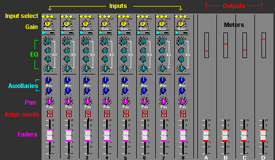
Flow Charts / Block diagram. Mixing desks have basic features in common but each feature can vary in complexity. The inputs may or may not have phantom power available for microphones with internal pre-amps. The EQ may be a simple (bass and treble) control similar to domestic sound systems or a complex parametric system that allows for any band of frequencies to be selected and adjusted. The auxiliary sends may or may not be switched pre or post EQ, and or pre or post fader etc. Some mixers have 1 or 2 independent stereo input channels whereas other designs require 2 separate channels to be used with an external locking bar for grouping 2 faders. Mixing consoles in recording, film and TV studios may be modified after purchase to enable a greater range of flexibility.

 All mixers are supplied with a block diagram sometimes described as flow charts. A flow chart or block diagram is not an electronic circuit, but a representation of the circuit layout. It is essential to understand flow charts to be able to know what functions the mixer has and the order in which the functions are arranged. Flow charts also show what parts of the mixer can be externally accessed or separated, and which parts are not accessible.
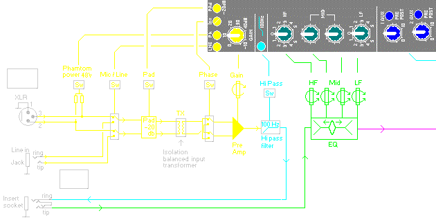
(a) Balanced Inputs The example flow chart below, of a single channel shows that the input can be selected for a balanced XLR mic or a line level jack plug. Balanced means that the mic signal is between XLR pins (2 and 3) and are not referenced or common to earth. This is done to stop electrical noise interference between earth and signal pins from being amplified. The balanced input circuit only responds to the signal between pins 2 and 3, and does not respond to interference noise which is common to the signal pins and earth.
The line input (jack) signal is attenuated (reduced) to a lower level similar to the mic level. In more complex mixer designs the line input has a separate pre-amp. A separate line level pre-amp is the best option.
A balanced isolation input transformer (TX) stops cable noise and other electronic interference from getting to the first pre-amp. Many mixers use a electronic circuit to achieve a similar result. The transformer is best option.
The first pre-amp also changes the input signal from balanced to un-balanced to be processed within the mixer. The signal is only made balanced again when re-sent from the mixer.
(b) Phantom power 48V is a technical trick to switch a supply voltage for powered mics to the XLR signal pins (2 and 3). This saves using extra wires or an external power supply and the reason for describing it as phantom power. This will be explained in more detail on the mic and cable pages.

(c) Phase switch The phase invert (Inv) switch is essential to manage different mics to insure they are in-phase when used collectively, eg. a drum kit. However there are interesting techniques of 2 mics that are used out of phase to create acoustic comb filter effects. Another technique is for live application where 2 mics are placed on top or beside each other and the vocalist only sings into one mic at close range. If the mics are out of phase the common background spill will be minimised.

(d) Gain Each channel has an input gain control. The pre-amp gain (volume) control increases the small mic signal (approx 10mV) up to line level (approx 1V). Fully clockwise increases the mic input signal X 100 (+40dB). This allows the input signal to be adjusted for the main fader to be put into the correct operating position.
(e) -20dB Pad Mic level is approx 10 - 100mV (1/100 - 1/10 Volt) Mixers have a -20dB Pad attenuation switch which reduces the incoming signal level to 1/10 (-20dB). This is required to avoid the first pre-amp from being overloaded (clipping) especially for dynamic mics with very loud singers at close range and mics placed close to drum kits.
Some loud pop singers only perform with the mic at or in their mouth. Screaming at close range and can cause a dynamic mic to produce 1V which can easily overload and distort the input stage. A simple recording trick is to allow the singer a mic to scream into at close range that is fed back to their headphones. The separate recording mic is placed at a correct distance, sometimes without the pop singer being aware.
(f) Hi-Pass Filter HPF limits low frequencies below 100Hz, to stop vocal popping and bass rumble. Some mixers allow the hi-pass frequency to be adjusted; this also is the best option.
(g) Insert jack The signal from the HPF is made available at an insert jack. This allows the signal to be processed through an external effect unit and then returned to the mixer EQ. Some mixers have extra inset jacks pre and post EQ and main fader.
(h) EQ equalization can be a simple bass treble or complex parametric, which allows frequency bands to be selected and adjusted.

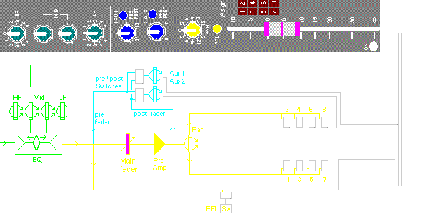
(i) Aux The auxiliary outputs are independent and can be switched pre or post main fader. Some mixers have many Aux sends. Some auxiliary sends are dedicated to pre or post fader including pre or post EQ, and some mixers allow the Aux sends to be switched from the different locations. The latter is essential for foldback which does not require the EQ that is selected for the assign recording output from the main fader.
(j) PFL The pre fade listen, or solo switch is beside the main fader. Some mixers enable the PFL function to be switched pre or post EQ. Some professional mixers have an independent VU or peak meter for each channel. But most basic mixers only have meters for the outputs. The PFL switch will connect that channel directly to one of the output meters for monitoring its level. As the EQ can change the channel level it is essential to check that the PFL is reading the post EQ position for the meter reading to be correct.
(k) Main fader and assign The fader pre-amp returns the signal to line level at the pan control, then to the 8 output selector switches (left 1,3,5,7) (right 2,4,6,8). All bus lines are sent to the output stages of the mixer and are also simple to follow.
Assign management and layout differs on each mixer. The above channel allows the operator to decide which of the output bus each channel is assigned to and for which purpose it is used. Some mixer designs assign the pan output to a separate A B or stereo bus.
www.soundcraft.com
https://music.arts.uci.edu/ Soundcraft Guide to Mixing pdf
https://sound-au.com/articles/audio-mixing.htm


