

When looking inside an amplifier the power supply is easy to recognise. The majority of power supplies in amplifiers are described as a 'capacitor input' supply. The description below is an overview.
1 Large mains transformer - toroidal or EI.
1 Bridge rectifier
2 Electrolytic capacitors
The mains transformer has a primary winding and two isolated secondary windings. The mains transformer steps down the 110V or 240V AC to 2 equal lower AC voltages. The power of a mains transformer is directly proportional to its physical size. However a 200W transformer is described as 200 VA and not 200W (volts x amperes = watts). The reason the power of a transformer is described as VA and not W is described in detail on sound-au.com/Transformers
The iron core can be a doughnut toroidal shape or a square shape described as EI. The iron core consists of thin layers of silicon soft steel, which has an excellent ability to conduct magnetic energy without retaining being magnetised. Therefore it can be alternately magnetised N-S and S-N at 50 or 60 times a second. 220V - 240V AC 50Hz UK Aus Europe or 110V AC 60Hz USA Canada etc.
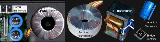
A common misconception is that toroidal transformers are more efficient than square EI transformers, but this is not so. For the same mass a square EI transformer will be slightly more powerful and have superior regulation, but EI transformers externally radiate the AC magnet field which can induce eddy current loops into the chassis and nearby components causing hum problems. EI transformers are cheaper, toroidal transformers are more expensive to make. The primary advantage of toroidal is that they radiate virtually zero external magnetic field, therefore correctly suited for audio amplifiers.
The traditional way to draw a power supply is from left to right. The example transformer in the below pic clearly shows that the primary and secondary windings are completely isolated from each other. Primary and secondary winding isolation is also essential for electrical safety. The AC voltage on the secondary winding is simply adjusted by the ratio of turns between primary and secondary. As an example, if the primary has 1,000 turns and the secondary has 100 turns (Ratio 10:1) 240V AC on the primary will result in 24V AC on the secondary. The mass of copper wire on both primary and secondary must be approx equal.
Primary 240W at 240V AC = 1A.
Secondary 240W at 24 V AC = 10A.
Therefore the secondary wire gauge must be a larger diameter to conduct 10A. The description given is a guide however in a real transformer there are losses of efficiency which have to be calculated for. Efficiency loss of magnetic coupling between the primary and secondary windings plus the resistance of the wire length in all windings that has to be adjusted for in the turns ratio.
The bridge rectifier (bridge) converts the 24V AC to DC. The electrolytic capacitors are similar to storage batteries that can be almost instantly charged and discharged repeatedly for an indefinite period.
The power supply must be mechanically wired in the exact order shown in the above pic. The two secondary windings are in series. The point where they are connected is named centre tap (CT). The CT is wired directly to the junction of the two electors. Only from the junction of the electors is the CT connected to chassis. If the CT was connected to chassis at the transformer an induced hum loop could be injected into the amplifier. Also, the supply rails must be wired directly to the terminals of the electors and not from the bridge. Mechanical wiring order is uniquely essential to power supplies. Many early musical instrument amplifiers had hum loop problems caused by external magnetic field of EI transformers and power supply mechanical wiring.
A bridge rectifier has 4 diodes. A bridge can be as a single unit with 4 internal diodes or 4 separate diodes. The diodes are arranged in order so no matter which way around the voltage polarity appears at the junction of each pair of diodes, from AC or a rotating battery, 2 diodes will be in the forward direction pointing toward the -V end of the example AC rotating battery, and 2 diodes will be in the reverse direction (open circuit). The polarity at the supply rails will always be the same and therefore correct. Remember, there is a 0.65V (650mV) loss across each diode in the forward direction.
A single primary winding is rarely used because of different AC mains voltages throughout the world. Therefore most mains transformers have two primary windings which can be connected in series or parallel. For countries with 110V 60Hz AC USA Canada etc the two primary windings are connected in parallel. For the countries with 220V or 240V 50Hz AC Europe UK Aus etc the two primary windings are connected in series.
The above pic shows how 24V AC is converted to the +V supply (vice-versa for the -V supply). The +V peaks of the sine wave appear 50 or 60 times / second (50Hz or 60Hz) which is each 20mS or 16.6mS.
mS = milli-Second.
The bridge rectifier reversus the polarity of the -V half of the sine wave so the +V peaks appear 100 or 120 times / second (100Hz or 120Hz) which is each 10mS or 8.3mS.
This is now described as pulsating DC.
The electrolytic capacitor charges up (similar to a battery) to the peak of each +1/2 of the sine wave. As the pulsating DC drops back to zero the electrolytic capacitor provide power to the amplifier. The capacitor starts to discharge from +32V down to +28V which is a drop of 4V (12.5%). This is described as ripple voltage and should not decrease less than 10%.
However, 10mS or 8.3mS later the next peak of the +V 1/2 of the sine wave charges up the capacitor again and again and again. By looking closely at the drawing each charging cycle only takes place for a very small period of time approx 1mS to 0.8mS. This small charging time is named the duty cycle. Also, it is only during this small time that power is provided from the mains transformer. The duty cycle charging time is only 1/10 of each cycle, therefore the charging current amperes has to be x 10 greater than the average being supplied to the amplifier from the capacitor.
When no power is being delivered to the speaker the ripple decreases to almost zero and only increases with the current amperes demanded upon the power supply. Increasing the size of the capacitor reduces the ripple voltage. As a rule of thumb 2,000uF is the minimum value for each 1 ampere of current. A power supply that has to provide 5 amperes will need a 10,000uF capacitor. Obviously the larger the capacitor the better.
Because the power supply is only charging the capacitors at the peak of each cycle for only 1/10 of the time means the overall efficiency of a 'capacitor input' power supply is approx 70%. This also means that a mains transformer rated as 200VA (200W) will only be able to provide approx 0.707 of its rated value. If the amplifier is approx 70% efficient and the power supply is approx 70% efficient then the power taken from the 110V or 240V mains supply will be at least x 2 greater than the power delivered to the speaker.
However, because an amplifier can not be driven with music greater than 1/3 of its capacity with a sine wave, the size of a power supply does not need to be greater than its full power rating into a speaker. A very large power supply has better + - V rail supply regulation. The only disadvantage of a large power supply is mass. The mass conventional power supply will be slightly less than 1kg / 100 VA (Watts).
Power factor
Power factor is the result of volts x amperes = watts. This may appear obvious but when AC is converted to DC to make a + - V supply, the power factor requires attention and further understanding. We shall begin with a simple battery and light bulb.
1V5 x 0A = 0W. Open circuit across the battery. Maximum V but 0 A.
1V5 x 1A = 1.5W. With a light bulb across the battery.
0V x ∞A = 0W. With a screw driver across the battery 0V but maximum A.
Volts without amperes, and amperes without volts, results in 0 watts. The electronic description is, volts and amperes are out of phase with each other. The degree to which V and A are out of phase results in a decrease of power W. Power factor phase is an in depth study in electronics. Hopefully the simplified explanation on this page is sufficient to obtain a basic understanding.
1V5 x 0A = 0W. V A is -90deg out of phase.
1V5 x 1A = 1.5W. V A is in phase.
0V x ∞A = 0W. V A is +90deg out of phase.
In a 'capacitor input' power supply the current A from the secondary of the mains transformer through the bridge rectifier is only charging the electrolytic capacitor for 10% of the time. Therefore amperes and voltage are only in phase for 10% of the time during the whole sine wave cycle. This 10% power factor is reflected back through the primary winding to the 110V 240V AC mains supply.
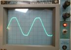
The oscilloscope in the right pic shows flattened tops on the mains supply system. This is the result of vast numbers of 'capacitor input' power supplies of all the electronic equipment on the AC mains supply. Taking current from only 10% of the mains supply sine wave instead of taking current continuously across the sine wave has created large mains power regulation problems throughout the world.
Switch mode power supply
Many household white goods, refrigerators, steam irons and electric ovens are simply controlled by being switched on and off. As the refrigerators warms up it is switched on until it cools down, then it is switched off again and so on. Electric ovens and steam irons function in reverse way. The time it is switched on compared to the time it is switched on is the duty cycle. duty cycle is measured as % of on time compared to off time. A refrigerator with a permanently open door would have a duty cycle of 100%. With the door closed the duty cycle may be only 10% depending on the quality of insulation. A refrigerator may be on for 5 minutes and off for 50 minutes and so on to maintain cold temperature. The longer the time span (clock speed) of the duty cycle the greater will be the temperature difference between on and off. &The fastest time a refrigerator may be able to turn on and off would be approx 1 minute. Therefore it would have a clock speed of 1 minute. If the refrigerator had a higher clock speed of 1 second (1Hz) so it could be turned on for 1 second and off for 10 seconds maintaining the same duty cycle of 10% the temperature would be controlled more evenly.
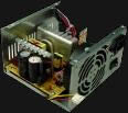
With a conventional 'capacitor input' power supply the mains frequency of 50Hz or 60Hz can be described as the clock speed. A 50Hz or 60Hz clock speed is very slow and the reason for the large ripple in the supply rails. &If the mains frequency was 1kHz then the ripple on the supply rails would be virtually non existent. Switch mode power supplies in computers and most home entertainment systems DVDs and plug packs etc have clock speeds of 25kHz to 100kHz. A computer switch mode power supply does not use a large heavy mains transformer. The advantage of a switch mode power supply is reduced mass, but its circuitry is extremely complex and virtually un-serviceable.
The mains voltage is fed into through an electro magnetic interference (EMI) filter into a bridge or voltage doubler (VD) rectifier and converted directly to DC. Most switch mode supplies are internally designed to function between 280V DC to 340V DC.
240V AC mains x 1.414 = 340V DC with bridge rectification.
110V AC mains x 1.414 x 2 = 310V DC with voltage doubler rectification.
The EMI filter stops Rf (radio frequency) switching noise generated by the switch mode power supply from getting back out into the 110V 240V mains system effecting other equipment connected to the mains. There are strict international regulations governing the maximum Rf radio frequency noise that electronic products must comply within. This regulation is named C-tic.
(1) The mains rectified 300V DC approx is switched on and off through a transformer. The MOS-FET act as a switch. The switching speed can be between 25kHz and 100kHz. The PWM (pulse width modulator) controls the duty cycle of the switching frequency which is similar to a square wave that has variable width. The transformer is specifically designed for switching frequencies of approx 50kHz. High frequency transformers are very small and therefore have little mass.
(2) The secondary of the transformer reduces the switched AC pulses to a lower voltage, plus isolating the mains to ensure electrical safety. The diode then converts the secondary pulses to the required polarity. The secondary electrolytic capacitor smooths out the 50kHz DC pulses to an almost perfectly smooth DC supply.
(3) The secondary voltage is fed back into a comparator within the pulse width modulator (PWM). The PWM then automatically adjusts the width (duty cycle) of the turn on and off pulses to the power MOS-FET which acts as the high frequency switch, controlling the current amperes through the primary of the high frequency transformer, which in turn corrects the voltage at the secondary to insure that the output DC voltage is exact.
The high switching frequency gives the switch mode power supply a unique advantage of providing a near perfect ripple free smooth and regulated DC supply voltage that does not decrease in voltage as extra current is required.
However, switch mode power supplies are extremely complex. The high switching frequency technology is in the Rf radio frequency band. This causes major headaches to technically manage containing Rf radiation from the printed circuit tracks and connecting wires within the circuit getting to the outside world and causing Rf noise contamination in radio and TV. Also, the circuit operation is extremely fragile and if any fault occurs (no matter how small) it contaminates almost every sector of the circuit.
Switch mode power supplies are non user serviceable, failures are simply dealt with by trashing the power supply and purchasing a new one. Attempting to service a switch mode power supply is virtually out of the question, except for fanatics who have infinite time. The technology is so complex and fragile that reliable operation after 7 years is not always expected but considered a blessing. As the world converts to using switch mode power supplies and PWM Class D audio amplifiers, they will eventually end up as the dominant mass of rubbish land fills.