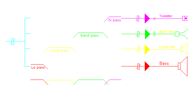
Active systems can be 2-way, 3-way, or 4-way. The signal from the pre-amplifier or mixer is electronically filtered into the correct frequency bands to be sent to independent amplifiers that drive the bass speaker, mid speaker and tweeter separately. The auditory difference between an active and passive speaker system is noticed by everyone. A correctly set up active sound system has greater clarity and realism and free from inter-modulation distortion. For an active system to be compact and affordable the amplifiers can be included within the speaker cabinets.
Traditionally, the audiopile retail market had been opposed to selling active systems, but this is changing. Audiophile retailers make greater profits marketing magic and mystical components, not technology. Magical speakers connected to magical amplifiers with magical cable producing a magical sound which only they can hear. This may sound silly but these fraudulent business practices are real and highly profitable. The Pro-audio market is mostly driven by brand image and trends, rather than technology. Merchandisers gain greater control in how they profit from a sale by selling speakers, cable and amplifiers separately. The primary problem is greed, ego, ignorance, fear of technology and lack of education. Also most sound engineering courses are superficial with little or no meaningful electro-acoustic content.
But there is a paradox, an incorrectly set up active system will perform worse than a correctly set up passive system. Active systems require technical skill to set up correctly. People who make speakers systems rarely have electronic knowledge. Most electronic people have limited electro-acoustic knowledge. Most active applications are 2-way. An extra amplifier and speaker for sub-bass. Active systems are often used for high-powered professional applications. Active is rarely taken to its fullest extent as a 4-way across the frequency spectrum, because of cost, time and limited technical understanding to manage the complexities.

Electronic crossovers can be purchased as 2-way and 3-way for stereo but rarely as a stereo 4-way. Crossover points can easily be changed. Slope (2nd order) 12dB/octave (Q 0.707) -3dB at crossover point (Butterworth) will give the best performance with least complications. Higher order slopes 4th order 24dB/octave with -6dB at the crossover points can be utilised to provide greater control over the speakers, but are more critical to calibrate.
DSP Digital Signal Processing is the modern way electronic crossovers are managed. DSP is a high powered computer chip with dedicated firmware/software to perform the electronic crossover function. The audio signal is digitised, A/D converter, then processed by an internal computer and re-converted back to analogue, D/A converter. The software is modelled on the earlier analogue electronic crossover designs, so the procedures of management are the same. But, DSP systems have lots and lots of extra features that allow for almost infinite detailed control of the frequency spectrum. However, an extra lifetime maybe required to learn and apply the extra features.
Compression drivers with horns and compression bullet tweeter must have a Capacitor in series with the amplifier. The turn on/off pulses and DC offset, from amplifiers could easily destroy a compression driver and tweeter. 47μF for the compression driver and 4.7μF for the bullet tweeter will provide an extra -6dB/octave roll off . This will insure no bass energy will get to the drivers.
Professional Benchmark
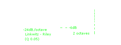
Linkwitz-Riley. Professional electronic crossovers referred to as Linkwitz-Riley, have fixed slopes, fourth order 24dB/octave (Q 0.5) and -6dB at crossover point (Bessel). The crossover points can be changed. This has been adopted as the standard for professional systems. The steep 24dB/octave slopes give maximum protection, control and power capability for the drivers. This Linkwitz-Riley bench mark is a mathematical calibration that is often dependant on the listener being unable to make changes once the system is calibrated. www.linkwitzlab.com

Theory behind this method is comprehensive and can be questioned, not as being right or wrong, but suited to the outcome. One part of the theory states that, at the crossover point, sound comes from 2 sources, acoustic directivity is increased, therefore power to each speaker should be reduced -6dB (1/4). This increased directivity is on-axis only, off-axis energy decreases. The total sound energy remains the same. For near-field monitor listening, -6dB at the crossover point can be argued as correct but for far-field -3dB can be argued as correct.
This Linkwitz-Riley bench mark is dependant on the listener being unable to make changes after the system is calibrated. But with active systems, level to each speaker can simply be changed to whatever balance the listener wishes to enjoy. Choice to change levels between speakers for personal musical enjoyment makes bench marking technically meaningless. The decision between right and wrong, now becoms one of choosing or not choosing the right to choose.
Listen to a mid speaker crossed over in isolation. 2nd order 12dB/octave crossovers attenuate the music without hearing a tone or colour change. Higher order crossovers attenuate the music causing a subtle but noticeable tone or colour change (hardening) in the music. When recombined with the other speakers this tonal change is not directly noticeable.

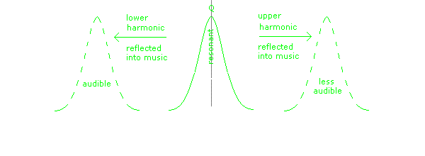
Active Crossover are created by electronic L. C. resonant circuits, or software digital assimilations of them. The slopes of crossovers represent a part (one side) of a resonant note. This note is not heard directly, but the steep slopes of third and fourth order crossovers can reflect harmonic interference (sideband distortion) within the music. Early research referred to this ghost resonance as transient distortion. Conclusive research in this area has not been completed.
Filter Shapes
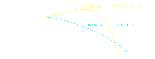
Chebychev, Butterworth, Bessel. These names are often used by people who wish to impress but do not know what they mean. These names honour early physicists and represent the math behind filter shapes, used by electronic design engineers. The Q of the slope (Quality of resonance), refers to the circuit, and its D (Damping), including the geometry of shifting phase in the slope.

Some electronic crossovers are designed for research and use computing power to change filter shapes, slopes, crossover points and time alignment. These crossovers are complex to set up. Roadie sound engineers (often stoned) love to randomly twiddle with these functions during live performances. This irresponsible behaviour often guarantees distorted colouration in the sound system and destruction of compression drivers.


