

For home use a 3-way passive speaker system is cost effective and adequate for most people. It is possible, but not practical, to make a 4-way passive crossover system. To make a 3-way passive system into a 4-way, the bass (sub-bass) should be active (driven by a separate amplifier).
Speaker systems comprising of woofer, mid and tweeter and driven by one amplifier are called passive. Passive refers to the components (inductor and capacitor) between the amplifier and speakers. These components separate the frequencies so bass goes to the woofer and high frequencies to the tweeter.
The capacitor and inductor can be in simple or complex arrangements. Passive crossovers are effective but not accurate, requiring energy from the amplifier to function (insertion loss). They reduce efficiency of the speaker system and contribute to distortion, especially at high power.
L Inductor mH (a coil of wire) limits high frequencies going to the woofer.
C Capacitor μF (like a small instant re-chargeable battery) limits low frequencies to the tweeter.
A single capacitor and inductor (6dB/octave) are used for cheap 2-way speaker systems but does not give sufficient control to accurately manage quality speakers. A capacitor and inductor shifts phase 90deg to the speakers in opposite directions.
What is an L-pad?
L-Pad is a level control used in passive speaker systems to attenuate (reduce) power to the tweeter in a 2-way system as well as the mid speaker in a 3-way system. Most mid range speakers and tweeters are approx +6dB more efficient than woofers. Inside the L-Pad are 2 wire wound elements arranged to maintain a constant impedance of 8R to the amplifier.
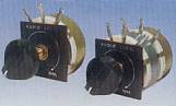
An L-pad can be purchased as a variable control (single or dual), as in above pic.
Variable L-pads are for 8R speakers only. For 4R speakers, use a dual 8R variable L-pad with both sections in parallel. L-pads can also be made with fixed values of large wire wound resistors. For 4R speakers the value of the resistors is 1/2.
L-pad fire warning. An L-pad adjusted to attenuate power by -3dB will allow 1/2 power to the speaker and the other 1/2 power as heat in the L-pad resistors. The resistors should be as high power rating as possible. Not less than 20W.
How does a 3-way passive crossover work?
An L inductor(mH milli-Henry) approaches being a short circuit at low frequencies and an open circuit at high frequencies. C capacitor (μF micro-Farad) approaches being an open circuit at low frequencies and a short circuit at high frequencies. The impedance of L and C (expressed as the resistance they represent), at any one frequency, is called reactance, symbolised by the letter X. This reactance changes x 2 or 1/2 for each double or half the frequency (6dB/octave).
The reactance XL and XC reduces power by shifting the phase between volts and amperes (of the signal) in opposite directions. The phase shifting of the signal at the crossover point has to be compensated by reversing connections to one of the speakers or by other means. A physical experience of phase shift is being in a motor vehicle that is accelerating or breaking, being thrust forward or backward, or the force sideways when going around a bend.
12dB/octave A 3-way passive crossover provides effective management of speakers. To extend a 3-way passive system to 4-way, the bass (sub-bass) should be active because sub-bass speakers are inefficient and require extra amplified power.
Bass (low pass). The inductor L1 in series with the bass speaker approaches being an open circuit at high frequencies (6dB/octave). The capacitor C1 across the bass speaker approaches being a short circuit at high frequencies (6dB/octave). Therefore the inductor and capacitor, when combined, limit high frequencies getting to the woofer at -12dB/octave.
Bass to mid-range (band pass). The second capacitor C1, in series with the mid-range speaker, approaches being an open circuit at low frequencies (6dB/octave). The inductor L1, across the mid-range speaker, approaches being a short circuit at low frequencies (6dB/octave). The inductor and capacitor, when combined, limit low frequencies getting to the mid-range at -12dB/octave.
Mid-range (band pass).The inductor L2, in series with the mid-range speaker, approaches being an open circuit at high frequencies (6dB/octave). The capacitor C2, across the mid-range speaker, approaches being a short circuit at high frequencies (6dB/octave). The inductor and capacitor, when combined, limit high frequencies getting to the mid range speaker at -12dB/octave.
Tweeter (high pass). The capacitor C2, in series with the tweeter, approaches being an open circuit at low frequencies (6dB/octave). The inductor L2, across the tweeter, approaches being a short circuit at low frequencies (6dB/octave). The inductor and capacitor, when combined, limit low frequencies getting to the tweeter at -12dB/octave.
Danger. The reactance (X) of L and C shift phase between volts and amperes, therefore reducing power (watts). L and C are in series, and phase is shifted in opposite directions between them. This is called a 'series resonant' circuit. If the speaker is not connected to the crossover, or the speaker has been destroyed (open circuit), the LC 'series resonance', without a load, behaves as a short circuit at the crossover frequency only. A solid-state transistor amplifier can easily be destroyed, but this will not harm a valve/tube amp.
12dB/octave passive crossover design
At the crossover frequency, XL and XC must = root 2 (1.414) of the speaker impedance.
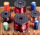
L inductors may have approx 150 - 300 turns of 1mm wire.
The resistance of the wire can be between 0.5R - 1R. This can be included in the calculations.
Capacitors may be between 4.7μF - 47μF
Capacitors should be non-polarized and ≥ 100 volt rating. Non-polarised electrolytic capacitors for speaker crossovers are expensive. Two ordinary electrolytic capacitors in series and back to back will often work just as well, maybe not as academically accurate as the more expensive non-polarised electrolytic designed for speaker crossovers, but its unlikely you will hear any difference.
Speaker impedance should be measured at the crossover frequency. The specified impedance will be accurate for the majority of dome tweeters, including bullet tweeters and compression drivers. Most cone speakers will be accurate between 200Hz - 600Hz. An 8R speaker will be 8R, a 4R speaker will be 4R, but from 600Hz and above (upper voice), most cone speakers will have a higher impedance than specified.
- R or Ω, measured in Ohms - is constant resistance over frequency.
- XC capacitive reactance, measured in micro-Farads (μF) - is variable impedance over frequency. (Amperes leads volts 90deg)
- XL inductive reactance, measured in milli-Henry (mH) - is variable impedance over frequency. (Volts leads amperes 90deg)
- Z impedance, measured in Ohms - is variable resistance over frequency with any combinations of (R - XL - XC)
Some designers go into extraordinary detail to adjust for the rising impedance of the mid speaker. Adjustment for this rising impedance does make the crossover technically accurate. This correction has little effect on musical performance and no effect on the reliability of the speaker or amplifier. Often, only the designer can hear the difference and if you are the designer you can choose to do it.
The exceptions. 18dB/octave passive crossovers are essential in professional systems for stopping low frequencies getting onto compression drivers. These drivers are expensive and can easily be destroyed with a few watts of power at low frequency. Many of these systems are small, portable 2-way passive speaker boxes, (12in - 15in and horn).
Passive crossover danger. The reactance (X) of L and C, shift phase between volts and amperes, therefore reducing power (watts). L and C are in series and phase is shifted in opposite directions between them. This is called a 'series resonant' circuit. If the speaker is not connected to the crossover or the speaker has blown up, the LC 'series resonance' becomes a short circuit at the crossover point. A solid-state transistor (not valve/tube amp) can easily be destroyed.
There are many excellent books, web sites and software programs that give precise construction detail and formulas for passive crossover design, but these require good math skills and basic electronic knowledge.
Magical passive crossovers
Passive crossovers of higher order than 12dB/octave can be made but are difficult to construct. Most are inefficient and inaccurate, regardless of the academic theory that describes them as being superior. The more complex a passive crossover, the more energy is required from the amplifier for it to function. This increases insertion loss which generates distortion that often outweighs the benefits.
Early research, referred to 'transient distortion' as the major problem of passive crossovers greater than 12dB/octave. Early audiophiles only accepted first order crossovers, claiming this has the least effect on colouring the music. Their descriptions were, "1st and 2nd order crossovers allow the sound to be open whereas higher order crossovers cause the sound to be closed".
Recent audiophile trends are for very complex passive crossovers, greater than 12dB/octave and that use magical capacitors. The larger the number of magical capacitors the more magical the sound becomes. These passive crossovers attempt to adjust for time alignment and impedance variations within each speaker. Often, only the designer can hear the difference, which becomes self-perpetuating to justify the design time spent and the cost of magical components. In almost every case (though there are exceptions) where these magical crossovers are replaced with a straight forward 12dB/octave crossover, the system springs to life. However, active crossovers cannot be generalised in this way.