

1. Alignment by traditional method
The cinema industry evolved before Radio and TV, therefore the later broadcast engineering standards were not applied. Some cinemas do the best they can to provide the highest quality vision and sound possible but there is no requirement for a cinema to have identical left-centre-right speakers, amplifiers or calibrated gains, to any other cinema.
The Dolby processor alignment approach is based on adapting to the way the cinema industry evolved. The Dolby processor enables the whole result, from the AB chain, heard by the audience, to be calibrated from within the processor decoder. The recorded sound on the film stock, projector, sound reader, decoders, noise reduction systems, EQ's, amplifiers, speakers, and acoustics are managed as a single entity.
This grouped procedure of alignment is unique to cinemas. It was introduced to simplify the procedure for non-technical people. Many audio and broadcast engineers of the cinema industry do not agree with this traditional cinema grouped alignment method. Professional recording studios and the broadcast industry align each item independently with absolute accuracy, usually done by electronic engineers.
Grouping the whole A and B chain as a single entity is error prone and often results in chaotic outcomes with large differences between cinemas. One of the many limitations of the combined alignment procedure is that if any one item within the AB chain is modified or changed without an external 0 VU reference level, then the Dolby processor calibration should be repeated; which is rarely done.
Most alignment procedures are done with pink noise and it is essential to understand what this means. White noise is random noise we hear as hiss over the entire frequency spectrum created by all electronic circuits. White noise is also created in nature as wind rustling through leaves or surf at the beach. White noise has equal energy per cycle. As the frequency (cycles) doubles (for each octave), so does the noise energy (+3dB/octave), resulting in white noise sounding trebly, as hiss.
Pink noise is filtered white noise so each octave has equal energy, therefore has a flat energy response and is similar to music and useful for acoustic measurements and approximations (only) for sound system alignment. This point needs to be repeated. Sound system alignment by pink noise provides a simplified approximation only and is not an accurate method.
The basic procedure is to put 3 or 5 omni microphones spread out at two-thirds toward the rear in the cinema in the middle of the reverberant field. The mics are placed in a non-symmetrical random pattern so not to pick up standing waves. Pink noise from the Dolby processor is put through the sound system and the result is aligned so that the direct and reverberant sound energies combined give the required response.
85dB SPL reference. ('C' weighting) The most important reference for all cinemas from the pink noise sound level measurement is for the Dolby processor volume control to be set at No 7 at 85dB SPL in the cinema room. The surround level is then calibrated to -3dB as 82dB SPL. This reference is applied at the original recording, ensuring the audience will hear the sound at the correct level the film director intended, (with the processor level control set at No 7).
This general loudness alignment for the 85dB reference, inclusive of direct and reverberant sound, is universally accepted as being practical, but calibration for fidelity and articulation using this combined method are issues that are hotly debated.
Alignment problems. The near field response of the speaker system (within 3 metres) is negated, as the traditional alignment procedure only looks at the combined direct and reverberant sound energies toward the rear of the cinema. Depending on the acoustics of the cinema, the direct on-axis energy from the speakers is aligned to sound harsh or trebly, relying on the reverberant and added propagation bass energy from walls floor and ceiling, to fill in the difference.
Because there is no reference in the traditional alignment procedure to address the difference between the direct and reverberant sound, then this combined procedure of alignment, that includes the chaotic behaviour of the reverberant field, must seriously be brought into question.
Discerning music lovers and audiophiles only accept direct sound from a flat speaker system as having integrity. Recorded reverberation suited to the music is accepted. Unwanted reverberation from the listening environment (cinema) is regarded as chaotic noise. Using room reverberation (noise) as a filler reduces fidelity and intelligibility.
Division of opinions. Many within the cinema industry are content with the traditional procedure but just as many discerning people inside and outside of the cinema industry are dissatisfied. They believe that the fidelity of cinema sound falls far short of what can be achieved. It is argued that the majority of the public are not interested in how cinema sound sounds. But, there appears to be no un-biased research on the public discernment of the cinema experience.
Old JBL documentation of sound system application and alignment states that a sound level difference between the front to the rear of a cinema be less than 6dB. Considering that the direct sound energy would decrease approx 24dB for the inverse square law for an average large cinema, and the directivity of the high-frequency horn would give an approx 6dB improvement, that means approx 12dB of reverberant energy is accepted. It is difficult to understand how any intelligibility is heard with this level of reverberation at the rear of a cinema.
'X-curve' alignment
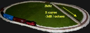
All cinemas are meant to be aligned to the creed of the 'X-Curve' without question. The X-curve was originally created to provide consistency to the traditional alignment method. The X-curve is a high-frequency roll-off beginning at 2kHz at -3dB/octave, then -6dB/octave from 10kHz. Various correction factors are given for different sized cinemas. ISO Bulletin 2969, 'Curve X' is also described in ANSI PH22.202M-1984 / SMPTE 202M.

There appears to have been an examination of many cinemas over 30yrs ago, and the X-curve is said to have resulted from pink noise measurements of an assumed average cinema. The observed result was that the low-frequency reverberation was greater than the high-frequency reverberation. This is understandable because concrete constructed cinemas with curtains on walls will readily absorb high-frequencies but have less effect on absorbing low-frequencies.
- Measurements were done at 2/3 toward the rear of the cinema to include the reverberant field.
- Equalization was then applied to the cinema speakers so the result would approximate the energy spectrum of recording studios monitors, heard at the position of the mixing console.
- The shape of the equalization applied to the cinema speakers is said to be the X-curve.
There are many who argue that the X-curve has no beneficial effect and has further complicated the original problem. Depending on the acoustics of the cinema, the direct on-axis energy from the speakers is aligned to sound harsh or trebly, relying on the cinema reverberation to fill in the difference. Critics say that the X-curve does not discriminate for fidelity and articulation as it makes no difference if the reverberant sound energy was replaced with 100 monkeys randomly bashing tin cans. All that matters is that the combined energy response heard by the cinema audience (regardless of what it consists of) is similar to the energy response of the original recording heard at the mixing console.
The detailed rationale and arguments behind the X-curve have not been fully explained to scientific and engineering people on the outside of the cinema industry, who are mostly unaware that the X-curve exists. 'Why is this so?' Please read these links.
rawsound.com/THX1 Tom Holman, Skywalker and THX
The X-Curve: Its Origins and History pdf
www.hometheaterhifi.com Cinema Sound and EQ by Brian Florian.
Bringing alignment procedures into question that have been practised without question for many years (generations), is similar to the emotional reactions when questioning religion without being able to mention God, or the questioning of God without being able to mention religion.
External reference. A possible reason for the lack of clarity about the X-curve is that it appears to have no external reference outside of itself. An external reference is essential for logical assessments, otherwise miss-conceptions occur. One example of logical discrepancy infers that; the larger the cinema, the greater the high-frequency reverberation. This implies that an infinitely large cinema would have infinite high-frequency reverberation. If the X-curve roll off is meant to compensate for this, then an infinite high-frequency roll off is required to compensate. (An infinitely large cinema would have zero reverberation because it would be a free-field).
In reality the same sound arriving at different times, from being reflected from walls and ceiling, can result in approx -10dB loss of high frequency energy toward the rear of an excessive reverberant auditorium or cinema. These cancellations are described as a comb filter, simplified in the below pic.
False assumption. It is easy to assume that the reverse could be applied, that is, regardless of the reverberation, including that the sound system behind the screen does not need to have a flat frequency response, it does not matter. Because, by placing a microphone in the reverberant field with a 1/3 octave graphic equaliser and simply adjusting the controls, the result can be made to align to the X-curve as if there was a flat speaker system behind the screen, similar to the recording monitor. Therefore it appears that a 1/3 octave graphic equaliser (or its equivalent) solves all problems.
Nobody is 100% sure of this because it is not directly stated. Different authoritative sources have different interpretations of this description. But, this reverse procedure based on assumption, regardless of how it is described, appears to have become the X-curve alignment.
wikipedia.org/Socrates Socrates would have difficulty accepting the logic of this approach if cinemas existed in his time. Obscure and subjective forms of acoustical alignment possibly existed with amphitheatres in ancient Greek times and definitely existed amongst organ pipe tuners. Piano tuners often tell humorous stories of this history.
Is it possible that many years ago a committee, established to address the sound alignment problem, decided to align sound systems to comply with the apparent roll off above 2kHz at -3dB/octave (heard at 2/3 of the distance from the screen) as a simple means to provide consistency between older cinemas that did not have acoustical absorption on walls?
Or was the obscure aim of the X-curve procedure possibly intended to provide a uniform energy response to compensate for reverberation in an assumed average 500 seat cinema, to which cinemas of all other sizes can be then be adjusted or somehow conformed to? Or was the X-curve procedure supposed to provide a common base-line between mixing rooms and cinemas?
A simple solution is to put a blanket over every cinema so all cinemas will sound the same. It is no more effective than if everyone put cotton wool in their ears, the outcome would be the same.
The objective behind this statement is not to negate the positive intention of those who originally initiated this idea many years ago, when circumstances were very different to today, but to challenge those who unquestioningly continue to practice this procedure by providing scientifically proven data to justify why it should be sustained.
Therefore, three rhetorical statements need to be made.
- Generalised assumption.
How specifically does the X-curve provide a uniform energy response or common base-line between mixing rooms and cinemas?
- Deletion of proof.
How or where is the evidence for a uniform energy response or a common base-line obtained?
- Distortion of logic.
How can changing RT with EQ be made comprehensible in logic?
Most modern multiplexes have pleated curtains on walls which effectively absorb high-frequencies plus high-frequency air absorption and screen attenuation, including that most front speakers are 2-way without tweeters; all together approximate the X-curve. When combined with the compulsory X-curve alignment procedure, it does not make logical sense and now appears as a contradiction.
The home cinema 're-EQ' for small room acoustics in THX approved systems is supposed to be a variation (whatever that means) of the commercial cinema X-curve. But there does not appear to be a clear unambiguous definition of sound alignment procedures in recording studios for the X-curve to be referenced to. There is no equivalent of this type of alignment in the live entertainment industry, and none of this has any effect on changing the reverberation time RT.
Recording engineers easily override the X-curve by boosting the high-frequencies when recording. As we know, film sound is brighter and harsher than music CD's. There is no absolute way of knowing what the final mix will sound like until the film is released. Recording engineers, directors and producers often go from cinema to cinema to check the differences. It is only from trial and error experience do recording engineers formulate their individual approaches to compensate for the X-curve alignment.
 Possibly the most technically flawed trend in audio history began in the 1970's with the marketing of parametric and 1/3 octave graphic equalisers for solving room acoustic problems, which continues to this day with the miss-use of digital signal processors (DSPs).
Fads and trends. The audio industry is without doubt the most fad driven industry in the world, wallowing in religious worshipping of silly beliefs, brand names and model numbers. From magical speaker cables to ex-roadie recording engineers belief that 'the good sound knob' is the largest one on a time-aligned valve compressor.
"Thou cannot equalize time with amplitude". This is the first commandment of acoustics. Trying to compensate for a reverberant venue (that does not allow proper stereo imaging and or poor fidelity speakers) with equalization is as silly as a dog chasing its tail, similar to the toy train in the below pic. "As punishment, thou shalt be plagued with poor dialogue articulation and annoying harshness".
Black arts. All techniques that use equalization for controlling sound system alignment in reverberant fields have no external reference in physics. This practice is only held in place by belief, which only the true believer hears. Many who make a living from this type of obscure acoustic alignment do not have benchmarks between themselves from which they are able to create consistent outcomes. These procedures do not require those doing it to have a background in acoustics and therefore refer to their craft as a 'black art' which they will defend to the death.
The following statement by John F Allen also states the problem.
"Of all the topics I have covered over the last 21 years, one of the most important - sometimes controversial - is the subject of cinema sound system measurement and equalization. Without a doubt, the misinterpretation of the present pink noise based measurements along with the improper equalization that results, are two of the most difficult and perplexing problems in world of motion picture sound".
www.hps4000.com The mythical X curve by John F Allen.
sound-au.com/dsp Critical view of DSPs in-correctly used for room alignment.
www.mkpe.com X-curve explanation at end of page.
www.acoustilog.com/eq_myth.html The EQ Myth by Alan Fierstein, dB Magazine.
www.hometheaterhifi.com Cinema Sound and EQ Curves by Brian Florian
This text is not meant to negate the practice of acoustical alignment, especially by those that are able to create magical outcomes. But, as the days of cult crafts and alchemy are long gone and we now have physics, why not use it.
2. Alignment by physics
The primary emphasis should be on using high-quality sound systems to begin with. Sound alignment should be for achieving the highest articulation possible regardless of the combined energy response. &A more practical approach is to calibrate the sound at or within the critical distance, at no greater than 1/3 of the distance from the screen, and definitely not in the reverberant field. This requires understanding and identifying critical distance, near field and reverberant field as being separate.
The only way to prove or disprove that the X-curve has any potential value, it first must have a reference outside of itself in a scientific context. This initial reference must be based on the original recording being monitored with a flat speaker system in an anechoic environment, and then heard by an audience in a anechoic cinema from a flat sound system.
This must be stated in the most succinct manner so no misconception can be interpreted from this theoretical reference. Therefore, any deviation from a flat anechoic reference that proves to be beneficial can be explained in a technical manner to insure accurate compliance and consistency.
Sound system technology is sufficiently advanced to enable flat 4-way active sound systems to be applied in mixing studios and cinemas. Building resources are readily available to create close to anechoic environments. The only acoustical alignment that should be required is for screen and air attenuation and compensating for lower frequencies from increased directivity (propagation) from the floor and walls (if necessary).
Projectionists are the backbone of cinemas, for without them the show couldn't go on. They should be applauded at the completion of each session. The problems previously stated could be better dealt with if the skills of projectionists were up-graded to full exhibition management. Unfortunately they are often not given the respect they deserve nor a say in how cinemas are managed. This oversight of their skill and knowledge is a reflection of the many problems that limit the industry's performance and economic viability.
Cinema sound alignment
engineered reference
All Radio, TV stations and recording studios throughout the world comply with international broadcast engineering standards for 0VU line level and calibration of every item within the entire broadcast and recording system. This provides consistency, reliability and most important, inter-changeability.
This text provides ideas only for thinking through the procedure. The steps are easy to follow, however each installer or management of cinema complexes must develop their own detailed procedures suited to their application. The installer must have a good command of dB conversion and ohms law. The Dolby processor is to be 0VU referenced and used only for its primary functions. All EQ within the processor is neutralised. EQ for cinema acoustics and or speaker system is done external from the processor.
85dB SPL. Broadband pink noise measurement at approx 2/3 distance in the cinema room for calibrating the Dolby processor volume control at the No 7 position. The pink noise bandwidth should be first limited to 500Hz - 2kHz for best alignment accuracy of voice frequencies. Then increased to broadband. But broadband pink noise is often the only option available. The reason many cinemas have inconsistent loudness levels is because the 85dB SPL reference can be applied in 4 different ways.
- 85dB from 1 screen channel inclusive of reverberation.
- 85dB from 3 screen channels inclusive of reverberation.
- 85dB from 1 screen channel at inverse square law (anoechoic).
- 85dB from 3 screen channels at inverse square law (anoechoic).
(1) 85dB from 1 screen channel inclusive of reverberation appears to be more consistently stated within various documentations. When all 3 screen channels are combined the loudness will increase 5dB to 90dBSPL.
(2) 85dB from 3 screen channels inclusive of reverberation is 80dBSPL from each channel and therefore the quietest alignment and is the preference of this text.
(3) 85dB from 1 screen channel at inverse square law (anechoic). When all 3 screen channels are combined the loudness will increase 5dB to 90dBSPL. Then with the reverberation added it may be 3 to 10dB louder again giving a total of 93 to 100dBSPL.
Loudness. The reason this text prefers option 2 is because 85dBSPL in a quiet cinema is experienced as being loud. Whereas in the streets of a noise polluted city 85dBSPL is not loud compared to traffic noise. Many earlier cinemas did not have acoustic absorption on walls and therefore had excessive reverberation. Reverberation has a similar effect to traffic noise pollution by masking dynamic range and requires one to shout to be heard. This is possibly the reason a loud alignment option was originally chosen.
Most modern cinemas are quiet by comparison to earlier cinemas, therefore the quieter 85dB alignment may now be the best option (No2). Many recording engineers monitor too loud and become deaf and then turn up the level to compensate. A cinema referenced at approx -6dB below recording monitored level appears to provide a more consistent result.
No7 = -20dBFS. No7 on the Dolby processor represents -20dBFS, therefore the maximum level available is another 20dB. This extra level is rarely used but it is available for special productions that require the audience to hear extreme sound levels. Hopefully for only short periods of time.
105dB SPL. The individual power from each of the left-centre-right speakers is meant to achieve 105dB SPL for maximum dynamic headroom. This means an extra 20dB (x 100 more power) above the 85dBSPL reference. When all 3 channels are combined the result will be an extra +5dB approx making a grand total of 110dBSPL. This extreme loudness is beyond the safety OH&S limit. Therefore the 110dBSPL measurement must be regarded as academic to insure there is sufficient headroom so no distortion is heard.
The 105dBSPL measurement should be referenced to free field (anechoic) and calculated at inverse square law. Alternative text refers to this as being 'first arrival' separate from reflected sound from walls and ceiling. The following examples are approximations for a +300 seat cinema with 2/3 distance being 16m (54ft).
- Inverse square law at 16m (52ft) = -24dB.
- Each speaker (2 x 15in + horn) approx 100dB/mW and 400W power rating.
- 400W is +26dB therefore sound level at 1m = 126dBSPL.
- At 16m (-24dB) the sound level at 400W = 102dBSPL.
- All left-center-right speakers at 1,200W gives an extra +5dB = 107dBSPL at 16m (54ft).
These free field measurements are -3dB short of the academic objective, but when the speaker system is applied to a cinema the reverberant energy will add a minimum of +3dB to these measurements. Therefore, a total sound level of 105dBSPL will easily be achieved with 400W amplifiers. A cinema with a 10dB reverberant field will only require 80W to each speaker to achieve the loudness objective, but intelligibility will be poor.
Alignment steps
 1. Speaker systems. The speaker system should be designed and calibrated to achieve the correct directivity and a flat frequency response in a free field environment. This measurement is done by placing the speaker box on its back in a large field facing upward and measured at 3m (10ft) above the speaker. This is similar to the speaker system being placed in a baffled wall.
Identically matched. The left-centre-right speakers must be identically matched before being installed. These measurements can also be achieved within a closed environment, however this requires greater skill and practice with extensive knowledge of acoustics and test equipment to assimilate free field conditions.
The speaker system is then placed in front of the screen and measured for how it sounds before placing it behind the screen. Providing everyone is happy, the speakers are permanently mounted behind the screen and re-measured. The speaker system will behave differently compared to the free-field measurement.
2. Sound system EQ. Independent correction EQ for lower frequency propagation from the floor (if necessary), including high-frequency boost for screen and air attenuation. These EQ adjustments must be identical to all 3 screen speakers. This can be done with an independent dedicated parametric system, a 1/3 octave EQ or a digital signal processor DSP. The EQ results must be double checked and logged for future reference. Use independent EQ for surrounds.
Although these EQ facilities are duplicated within the Dolby processor, it is strongly advised to use the processor for decoding only. Repeat - avoid the temptation to use the Dolby processor for anything other than its primary functions.
ensure that the horns are downward angled at the best position for voice articulation centre seating. Ensure the left-right toe-in gives the best stereo image possible. The toe-in may be required to be of a greater inward angle than anticipated.
As a general rule a toe-in closer to the screen and at an increased downward angle is required for excessive reverberant cinemas to help reduce reflections from side walls and ceiling.
3. Amplifiers. For all 3 left-centre-right speakers to achieve 85dBSPL at 16m, each amplifier only has to drive its speaker to 80dBSPL. For the quieter No2 reference as previously stated. 16m represents an inverse square loss of -24dB. Allowing for the reverberant field contributing approx +3dB, the inverse square law loss can be rounded to -20dB, therefore each speaker only has to deliver 100dBSPL at 1m for the sound level to be 80dBSPL at 16m.
2 Volts into a 4Ω speaker box is 1W, (V²/R = W) 2V x 2V / 4Ω = 1W. The speaker system is 100dB/mW efficient and will give 80dBSPL at 16m, which includes the reverberant energy. All 3 speakers will add +5dB giving the required 85dBSPL reference.
With modern 400W + amplifiers the power headroom calculations are no longer a problem and often do not need to be calculated. Power headroom calculations were necessary in earlier years when power amplifiers were less than 100W.
Amplifier gain. Amplifier manufacturers have not agreed to comply to voltage gain standards, which is irresponsible to say the least. Some amplifiers have un-calibrated attenuation (level) controls, but many have nothing. Calibrated attenuation (level) controls are absolutely essential. This problem causes wasted time and extra calculation headaches for installers. Amplifier gains vary between (26dB) 20:1 to 40:1 (32dB) or greater. Specified amplifier gain will be consistent to each model number only.
- Gain 20 = 26dB
- Gain 23 = 27dB
- Gain 40 = 32dB
Some amp specifications can be without reference to gain.
- 0dBu 0.775 V = 1/2 power
- 3dBu 1V = full power
4. Processor level. Line level 0VU (volume units) reference must be set for the processor. The highest 0VU reference level the processor can be set, is limited by the maximum signal level above the 0VU reference which is 20dB (x10) greater.
The internal supply rail voltage for the operational amplifiers is (+15V) - (-15V) 30V total. The maximum theoretical RMS signal Voltage at the on-set of clipping is calculated by (PP/2) x 0.707. (30V / 2) x .707 = 10V RMS approx. Allowing for a 3dB headroom reduces this figure to 7.07V RMS.
Therefore the maximum setting for an 0VU reference is (0.775mV) 0dBu for fader position No 7. The maximum signal output that can be obtained from the processor is another 20dB which is +20dBu (7.75V). All figures refer to unbalanced output only.
- From 0dBu (775mV) as 0VU +20dB = +10dBu (7.75V).
All DSP's (digital signal processors) have limited bit rate which simply means that it is not infinite. Applying internal equalization consumes large amounts of the available bit rate and the unfortunate result is that the internal noise floor is greatly increased. The signal to noise ratio (quantization noise) is directional proportional to processing usage. Some installers set the 0VU for the processor as high as possible to obtain the best signal to noise ratio.
wikipedia.org/Quantization
+4dBu (1.2V) as 0VU is the standard for the majority of recording studios, but with an added 20dB (x10) this would result in 24dBu (12V) well into clipping, therefore this 0VU reference cannot be used. Dolby recommend a typical 0VU calibration level of 300mV, which is very close to 315mV or 250mV, depending on various documents.
- From -10dBV (315mV) as 0VU +20dB = +10dBV (3.15V).
- From -10dBu (250mV) as 0VU +20dB = +10dBu (2.5V).
If the Dolby processor is set to 0VU reference of -10dBu (250mV) the output from the average film may vary between 20 - 780mV (36:1) approx 30dB dynamic range. Digital technology allows for a 99dB dynamic range, but because of inept recording practices that rely on excessive over-use of dynamic compression, film sound rarely has a dynamic range that exceeds 30dB. The majority of pop recordings are dynamically compressed to within 10 - 20dB, including TV and radio broadcasting.
5. .1 sub-bass. (SMPTE RP 200) The .1 sub-bass channel is meant to be set at +10dB above the OVU reference. The reason the .1 sub-bass channel is increased +10dB is because it is recorded at -10dB below the main channels. The procedure of recording the sub-bass at a lower level was first established with earlier analogue magnetic recording because loud explosion effects could easily overload the tape or recording console causing excessive distortion. The tradition has been retained with modern digital recording even though it is no longer necessary.
www.genelec.com/-10dB LFE level function 5.1 to sub-bass alignment.
6. Calibrated attenuation. If the amplifiers have level attenuation controls they can be used but only if they are able to be correctly calibrated and logged. Otherwise, turn all level controls fully clockwise so they are out of use. Mark each amplifier with clear identification as to its gain, then use an external attenuation system in the rack between the processor and the amplifiers.
The signal from the Dolby processor must go through the separate calibrated attenuation system to reduce the signal to the correct signal levels to each of the amplifiers. Our chosen amplifier has a gain of 20:1 (26dB). The 0VU signal level from the processor must be reduced to 100mV (-18dBu).
- 0VU (-10dBu) 250mV x 0.4 is reduced to 100mV (-18dBu) (-8dB attenuation)
- 0VU (-10dBV) 315mV x 0.315 is reduced to 100mV (-18dBu) (-10dB attenuation)
100mV to the amplifier input x 20 will give 2V at the amplifier output. The speaker system is 4Ω. (V²/R = W) 2V x 2V / 4Ω = 1W. The speaker system is 100dB/mW efficient and will give 80dBSPL at 16m which includes the reverberant energy. All 3 speakers will add +5dB giving the required 85dBSPL reference.
Surround gain. The surround channels should be -3dB below the OVU reference and finally adjusted by ear. Because the amplifiers for the surrounds may be different brands or models, their internal gains may also be different, therefore the attenuation to surround amplifiers has to be adjusted separately to achieve the correct level to the speakers.
The X-curve Yes, what "do" we do about the X-curve?
Choose different films that are used for reference and listen. Surprisingly, the sound may be absolutely fabulous and if so, do nothing else. However, some films are recorded with excessive high-frequency boost by directors trying to override the imposed X-curve.
First try switching out the high-frequency EQ boost for air and screen attenuation. This may coincide with obtaining the correct outcome. If so, arrange for this to be easily switched for the different films. But, be prepared to install a separate EQ unit that can be switched in or out when required. These final decisions make the installers life very interesting.
Overview rules- Reference Dolby processor to an 0VU level. Eg -10dBu at Fader position No7.
- Set Dolby processor for
(85dBSPL at No7) (surround delay) (-3dB less for surround level) (+10dB .1sub-bass level). - Do not use Dolby processor for anything else.
- Use independent attenuation for adjusting level to the amplifiers.
- Do not apply EQ or level correction that differs between the front speakers.
- Do not attempt to apply EQ adjustments for anomalies in the reverberant field.
Stereo music being played before the beginning of a film as a prologue greatly enhances the enjoyment of the cinematic experience, but check the CD result through the Dolby processor first. The matrix techniques designed to spread 2 channel stereo into the 5 channels uses various phase differences between the left-right channels which can possibly introduce annoying distortion in the surround speakers. The best approach is for the stereo music be sent to the left-right screen speakers and also in mono to the centre screen speaker at -3dB.
Microphones. For special presentation events that require people speaking on stage in front of the screen where a microphone is required. Avoid putting the microphone through the Dolby processor as it is difficult to manage. However, if there is no alternative, select the microphone to be heard from the centre screen channel only. Hearing a person speaking through the surround speakers may give an unnatural coloured sound with low articulation. Microphone feedback can easily destroy surround speakers, which has often happened.
Voice in films is naturally heard through the centre screen speaker. Because the speakers are 2/3 toward the top of the screen, microphone feedback is not a problem. The clarity of voice through the center speaker is superior in quality to the majority of PA systems used by musicians, and the articulation will be excellent.
Links
www.doctorproaudio.com
SPL calculator
www.sengpielaudio.com/calculator-db-volt
International reference and calculations for dBu dBV etc
www.sengpielaudio.com/calculator-db
dB volt calculator