A speaker voice coil is specified in Impedance, because its Resistance changes with frequency.
Impedance (Z) is Resistance that changes in reference to frequency (simple description).
Resistance (R) may also be symbolised as (Ohm) or the Geek letter omega (Ω)
8 Ω is the standard Z Impedance for speakers, measured at 400Hz.
4 Ω is the standard Z Impedance for car speakers.
This is because cars have a low Voltage supply, 12V battery, explained in amplifiers).
16 Ω was an earlier standard when only valve/tube amps existed.
Some guitar amp quad boxes still use 16 Ω speakers.

The above graph shows that speaker Z, for cone speakers, can change by 100s of % across the frequency spectrum. 400Hz is often used as the reference for quoting speaker Z, regardless of what range of frequencies the speaker is used for. This is one of the reasons speakers have wide ranging differences in how they sound when reproducing music.
To help keep the Impedance Z consistent, some high quality cone speakers may cover the pole piece with a copper cap or have a copper shorting ring at the top of the voice coil, which unfortunately reduces the efficiency of the speaker. Some tweeters and compression drivers have an Impedance Z that is semi consistent across the frequency spectrum.There are 2 reasons speaker Impedance Z changes
1. Back EMF, at bass resonance, described in the next paragaph.
2. Inductance of voice coil at high frequencies.
The voice coil, being a coil of wire, is an Inductor. An Inductor is a coil of wire. Wire wound into a coil will naturally pass low frequencies but restrict higher frequencies.
Back E.M.F. At fundamental resonance (Fs) a reactive effect called Back EMF, causes the speaker (Z) Impedance to rise many times. E.M.F. Electro Motive Force is a term that applies to electric motors and generators. Externally moving the cone causes the voice coil to generate electricity. A speaker can work just as well as a microphone especially for bass drums.
Fs is fundamental resonance. Fs is the natural resonance the cone will vibrate at when externally tapped by a finger. Similar to tapping a drum skin. The natural Fs of a speaker cone is measured in free air outside of the box. Hold the speaker in your hands (not connected to the amplifier) and tap the cone. It will sound like a drum skin. The system Fs is measured with the speaker inside of the box. A smaller box will cause the Fs to raise to a higher frequency. This is dependant on the box being sealed. Fs becomes more complicated with a ported box.
At Fs the cone vibrates naturally, almost of its own accord and because the voice coil is in a magnetic field it will partially generate electricity. It appears from the outside, that the voice coil Impedance Z has risen. At 'Fs' the speaker is also at maximum efficiency, requiring only the smallest amount of input signal for the cone to vibrate.
Natural Damping. If you put a screwdriver or a piece of wire across the speaker terminals (as a short circuit) (without the amplifer connected to the speaker) and tap the speaker cone it will sound dead. Also while keeping the short circuit across the speaker terminals, gently but firmly grip the cone between your fingers and try to move the cone back and forth, it will noticeably resist moving.
Electric motors. With many large industrial machines, when an electric motor is turned off, a short circuit may be placed across the terminals. With the power off, a spinning electric motor becomes an electric generator and shorting the input terminals will cause the motor to brake (Damped) and stop almost instantly.
Amplifier Damping. With a speaker (woofer) connected to an amplifer that is turned off (solid state not valve) tap the cone with a finger, notice its resonant frequency. When the amplifier is turned on (without music) notice the difference. The speaker will now behave the same as when a short circuit was placed across the speaker terminals.
Negative feedback. All solid state amplifiers are designed with negative feedback. The output of the amplifier is fed back to a second input (inverting input). Any signal that appears at the amplifier output (that was not from the amplifier) is fed back to this second inverting input and amplified in the reverse polarity, hereby shorting out any electricity generated by the Fs resonance of the speaker.
Valve amplifiers do not have a second inverting input connected to the output of the amplifier, therefore only have a limited ability to provide damping. This is the reason a speaker will sound more resonant and produce a greater amount of bass, with less power, when driven from a valve amplifier.
When solid-state (transistor) amplifiers were first invented and available on the market, it was noticed that a solid-state amplifier had to be almost twice as powerful as a valve amp to sound as loud. Few people today, including audiophile reviewers, understand why this is so.
Efficiency
We can now review speaker efficiency by including radiation resistance, frequency, wave-length and fundamental resonance. Efficiency of a speaker is frequency dependant as shown in the below pic. Efficiency specifications of speakers can be misleading, but this is not intentional. This also reflects the reason that musical instruments are not specified with efficiency. Simply too complicated.
The efficiency specification of a speaker is typically referenced at 1 Watt at 1k Hz measured at one point at a distance of 1 meter / 3ft. (dB/mW) This measurement shows the on-axis efficiency (directivity) of the speaker only. This measurement does not give the actual efficiency of conversion of electrical energy to sound energy, across the frequency spectrum.
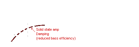
In reality, speakers are not measured at 1 Watt, but with a fixed voltage of (2.83 V) that would give 1 Watt if the speaker was exactly 8 Ω Ohm. At Fs fundamental resonance the speaker Z impedance could be as high as 32 Ω Ohm, and with 2.83 Volt this would be 1/4 of a Watt. This measurment is normally done with a typical solid state amp with negative feedback, and the natural Fs resonance of the speaker will be damped showing a large reduction of efficiency at Fs. A more accurately designed test procedure would have a switch to disconnect the negative feedback enabling the increased efficiency at Fs to be shown.
At the higher frequencies the speaker Impedance also rises, and can give a misleading efficiency reading. At higher frequencies (depending on the cone diameter) the directivity of the speaker increases to a beam, making it appear that the speaker is increasing in efficiency.
The efficiency specification of a speaker is relative to the application of listening at one point on-axis only, and not to the overall sound energy it produces at all frequencies. However if a speaker is fed with a constant power of 1 Watt (allowing the voltage to vary as the impedance changes) the efficiency measurement would look similar to the Impedance graph.
Tonal Quality

The tonal quality a speaker has when it is physically tapped by a finger is also the tonal quality it reflects in the music. There is no such thing as a speaker without its own tonal colour. Musical instruments and speakers share similar characteristics of the physics that governs tonal quality and sound colour. This physics has not yet been specified.
Resonance Q
The springiness of the suspension and mass of the cone, cause it to have a natural fundamental resonance like a drum skin. Q is a number specifying Quality of resonance (duration of sustain time). In some speaker systems, resonance is often tuned to the lowest bass notes in the musical scale, to help improve the efficiency of the speaker to reproduce the lowest bass notes.

Some manufacturers deliberately make the cone very heavy, shifting the fundamental resonance well below the musical range eg. 20Hz. Doping compound (tacky tar like substance) can be painted around the surround, damping the cone movement, reducing its Q at resonance. If this is overdone it can reduce speaker efficiency so it becomes virtually useless. There is a compromise between over damping the cone, to flatten its response, causing it to be inefficient and sound dead, or under-damping, allowing the cone to resonate (sounding alive) but will exaggerate the resonant note. This choice is personal. A Q of 0.7 may be optimly flat but sound dead. Whereas, a Q of 1.4 tends to be optimal for musical enjoyment.
Valve Amplifiers and Speaker Q
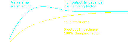
Complications regarding back EMF and fundamental cone resonance are often not fully understood by amplifier and speaker manufacturers. When technology changed from valve to solid-state it was noticed that solid-state amps lacked warmth (less bass) and had to be twice as powerful as valve amps to sound as loud.
Solid-state amps function in voltage drive (zero output impedance) (100% damping factor) and act as a short circuit across speakers' voice coil, effectively damping the performance. The larger the magnet and voice coil (BL) the greater the effect of damping. This becomes self-defeating for reproducing the lowest bass notes, and the primary reason for boxes to be ported to reproduce bass. However, there are other factors involved and this explanation needs to be expanded.
Speakers were originally made as efficient as possible. Early valve amplifier for domestic use were only a few Watts. The easiest way to make a bass speaker system efficient is to have a (lite) low mass cone, soft surround, with the speaker in a large box. The speaker would naturally be very resonant at the deepest bass notes.
When solid state amplifiers arrived, the resonance of the speaker was damped by the zero output Impedance of the solid-state amplifier which reduced the bass energy of the speaker well below the higher voice frequencies. The simple solution was to increase the mass of cone, which made the speaker less efficient. The efficiency of many speakers were reduced by approx 10dB. The zero output Impedance of a solid-state amplifier has less effect on further reducing the energy of the bass notes of a heavy cone speaker in comparison the higher frequencies. Also at the time solid-state amplifiers were first introduced social aesthetic changes in society preferred smaller speaker boxes as TV and Video became the dominant form of entertainment. Bass speakers with (heavy) high mass cones can work well in smaller boxes.
Solid-state amplifiers are capable of much greater power at lower cost (than valve amps) therefore speaker efficiency, or the lack of, is no longer a problem.
Valve amplifiers naturally function in current drive (high output Impedance) (less than 50% damping factor). Less damping allows speakers to function at maximum efficiency and the bass notes to be more resonant (subjectively sounding more musical). Valve amps are sensitive to speaker impedance variations. Some speakers had copper caped pole pieces, which helped damp impedance variations.
Had the understanding of amplifier output Impedance differences between valve and solid-state amplifiers been fully understood at that time, solid-state amplifiers would have had a control to vary between voltage and current drive to change their output Impedance to control the resonance of bass speakers, as a standard function.
A detailed explanation of amplifier output Impedance in reference to Voltage-drive - Current-drive as the reason for why valve and solid-state amps sound different is described in the amplifiers chapter.
Load Impedance
Review. R or Ω or Ohm, are the 3 symbols for Resistance.
Some text uses R for Resistance. Other text may use Ω or Ohm for Resistance.
Zero 0R is a short circut. Infinite ∞ R is an open circut.
Z Impedance is Resistance Ω that varies with frequency.
Load Impedance is the combined load speakers represent to an Amplifier. The maximum power rating of an amplifier is in reference to the load impedance.
for example; an amplifier rated at 100 Watt with a 4 Ω load, means, that only with a load of 4 Ω is this amp capable of 100 Watts.
With a load of 8 Ω this amp will only be capable of 50 Watt.
With a load of 16 Ω this amp will only be capable of 25 Watt.
The higher the load impedance, the cooler and more reliable the amplifier will be, and the lower (the better) the internal distortion figures of the amp will be.
However, with a load of 2 Ω this amp will attempt 200 Watt. The amplifier output transistors will get excessively hot and may fail. Heat is the enemy of electronic components. The more speakers connected to the amp the lower the load impedance, and hotter the amp will get. Accidentally shorting the amplifier speaker terminals, represents a load of 0 Ω and may destroy the amp.
1 x 8 Ω speaker the amplifier will only give 50 Watt run cool and reliable.
2 x 8 Ω speakers in parallel is 4 Ω 50 Watt into each 8 Ω speaker (100 Watt).
4 x 8 Ω speakers in parallel is 2 Ω 50 Watt into each 8 Ω speaker (200 Watt).
The speakers must not represent a load lower than amp Z rating.
The speakers can represent a load higher than amp Z rating.
Repeat-
An amp must not have a load, lower than the impedance the amp is rated for.
An amp can have a load higher than the impedance the amp is rated for.

Calculations
Speakers in parallel, divide speaker Ω by the number of speakers.
2 8 Ω speakers in parallel is 8 Ω / 2 = 4R.
4 8 Ω speakers in parallel is 8 Ω / 4 = 2R.
Speakers in series, x speaker Ω by the number of speakers.
2 8 Ω speakers in series is 8 Ω x 2 = 16R.
Speakers in series-parallel with even numbers of speakers only.
put each pair of speakers in series put each series pair in parallel with other series pair.
2 8 Ω speakers in series is 8 Ω x 2 = 16R.
2 8 Ω speakers in series is 8 Ω x 2 = 16R.
2 16 Ω pairs in parallel is 16 Ω / 2 = 8R.
4 8 Ω speakers in series-parallel = 8R.
The points
- Speaker Z load must not go below amp Z rating.
- Speakers in parallel or series must be identical.
- Speakers in series multiply speaker distortion but do not effect reliability.
- Speakers in parallel do not multiply speaker distortion.
Connecting speakers in series and series parallel may be essential in certain applications where many speakers are required to be connected to one amplifier. However connecting speakers in series causes the distortion of each speaker to be reflected into the others. But connecting speakers in series does not effect the reliability of the speakers or amplifier.

Speaker polarity Test The standard test for a speaker is to put a battery across the speaker terminals. When the + of a battery is put on to the + marked terminal of the speaker the cone should move out. This is also the correct test for checking the polarity of speakers in stereo systems. 1.5 Volt battery is safe to use.
Warning never use this test on a compression driver.


