

Acoustical absorption of furnishing and curtain fabrics against walls readily absorb high frequencies but have limited absorption at low frequencies. The greater the distance curtain fabrics are placed away from walls, the better the curtains are able to absob lower frequencies. The amount of sound energy absorbed depends on type of material, weight and pleating width. Rock wool (fibreglass) has the highest absorption capacity, converting molecular air movement to heat (at molecular level). Fibreglass consists of minute razor sharp fibres that are an irritant and need to be contained within fabric.
Brick, stone, concrete, reflect all sound. Timber, gyprock, steel, reflect most high frequencies and a % of low frequencies are absorbed by the wall. The remaining low frequency energy that is not reflected or absorbed, passes through the wall. Nothing can be done about sound that passes through a wall. Bass frequencies are the most difficult to absorb.
The 1/4 wave-length rule. Acoustical absorbent material must be placed away from walls and ceiling at a distance of 1/4 wavelength of the lowest frequency to be absorbed. This will include all higher frequencies if the absorbent material is soft furnishing or fibreglass. Please note that the ceiling should also be included. Understandably this will slightly reduce the physical size of the room. Acoustically the room will sound and feel LARGER. Also an acoustic absorbent environment (anechoic) is relaxing and calming.
Bass trap refers to distance the absorbent material is from a wall to include absorbing bass frequencies. Lowest frequency absorbed is governed by the material being at a minimum distance of 1/4 wavelength from a wall. Recording studios can have fabric up to 6ft / 2meters from walls. At 1/4 wavelength the molecular air movement is maximum, and is converted to heat by the absorbent material. The remaining sound that gets through the absorbent material is reflected back from the wall and again absorbed by the absorbent material.
Standing Waves are bass frequencies reflected back from walls and ceiling. The reflected bass interfere with the new incoming bass frequencies, causing cancellations, or magnifications at different points throughout the room. Each bass note will behave differently and the cancelled points will be in different positions. Moving speakers or listening position does not solve the problem. The only solution is to insure that the room is 100% absorbent at all bass frequencies. Standing waves also refer to how a string behaves on a musical instrument. There are excellent descriptions of standing waves on other web sites which include animation. Right mouse click to open in new window and allow time to download animation. While waiting to download continue reading.
There are many excellent videos and web sites on room standing waves and room modes. And videos of stringed instruments. Bowed violin string in slow motion.
Panel Absorbers There are many variations of acoustic panel absorbers. Simple panel absorbers are frames filled with fibreglass/rockwool or a non-irritant sound absorbent equivalent. The specifications of these panels are often in comparison to an equivalent area of open window space.
However there are complex panel absorbers consisting of large sheets of plywood formed into architectural shapes. These more complex panels can break up standing waves, deflect high frequencies and resonate (helmholtz resonator effect) to absorb bass energy. The formulas governing their behaviour are complex and the outcome is often unpredictable until constructed. Almost without exception they require time consuming trial and error modifications to get them to work as predicted. There are only a few acoustical architects that have mastered designing them. The below formula gives an approximation only.
fres = √60/md (fres = frequency of max absorption) (m = panel mass Kg/m2 (d = depth of air space in meters)
www.primacoustic.com
Anechoic chamber
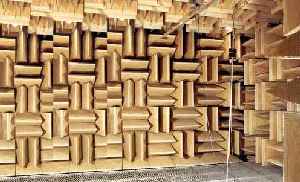
Anechoic chamber is 100% absorbant at all frequencies. No sound can enter or escape and the room is 100% silent. The closest we can experience this is in an open field, forest or desert on a perfectly still night. Simply described as free field. No sound is reflected or returned. Those who specialise in acoustics should experience being in an anechoic chamber, or spend time in a silent free field environment, to attain a reference. Surprising how different and revealing a sound system actually sounds in an anoechic enviroment.
There is a myth that being in a 100% anechoic environment is a negative experience. This myth needs to be well and truly busted. The myth possibly originated from experiments on university students during the 1950s, who were locked in a anechoic test chamber, to represent being buried alive in a coffin. Possibly, for someone whose ego is as big as the universe, being in an anechoic environment provides no acoustical reflection of their existence, and therefore this could be a stressful experience. But there are many, many accounts from those who have been alone, on mountain tops, open oceans or in arctic or antarctic regions who have experienced total anoechic silence and have been spiritually transformed.
Recording Studios
Recording studio control rooms often have walls and ceiling slope outward and upward, away from the speakers and screen. Absolutely no sound should reflect from the rear wall. For amplified performance including cinema's, all walls and ceiling, yes ceiling, should be as close to 100% absorbent as possible at all frequencies (free field).
Echo and excessive reverberation destroys intelligibility and enjoyment for the audience. Absolutely no echo must be allowed to be reflected from the back wall to the stage. The further away from the stage performance the more acoustically absorbent the room should become.
For live acoustic performance the stage walls and ceiling can have a small % of controlled acoustic reflection to enhance the performance. Only from the stage. Acoustic path lengths must be as short as practical. An exaggeration of short acoustic path lengths is a bathroom. Long acoustic path lengths are echoes (churches) and cause difficulty for musicians to play in time.
Sound system placement. Facing speakers directly forward adds excessive reflection from walls, and further reduces intelligibility. Many roadie sound engineers incorrectly mix in mono, in front of one speaker stack facing forward.
The speaker system should be turned inward to improve directivity, and minimise wall reflection. The angle that speakers could be turned inward can only be approximated by academic calculation. The most suited angle has to be found by trial and error. Wherever possible mixing should be from the centre, in stereo, where sound from left and right speakers intersects and at a distance no further back than where direct sound from the speakers is equal to the reflected reverberant energy of the room (Critical Distance). www.genelec.com/audio-music-education
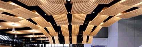
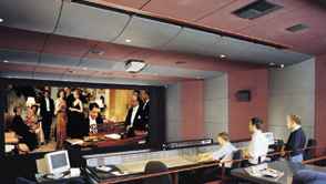
The above picture is to bring attention to the importance of acoustical absorption of ceilings. Many cinema complexes provide acoustical absorption on walls, but forget about ceilings. Below link is to a company that supplies and consults on acoustical absorption, with many excellent pictures of applications as above. www.acousticalsurfaces.com
There are many companies that supply acoustical absorption material and have excellent information on application and solutions. www.csrmartini.com.au www.rockwool.com www.acousticalsurfaces.com/
Architectural Acoustics
The information on this site is not meant to substitute academic text books. The aim is to prioritize the order of information to enable good acoustic design, often omitted in academic text.
An excellent referred text is 'Sound System Engineering' by Don and Carolyn Davis.
A Weighting sound measurement is non-linear and scaled in reference to our subjective hearing at low level. Our hearing is very sensitive at low level at the higher frequencies 500Hz to 4KHz, and less sensitive at bass frequencies. A weighting is used for noise measurement of office, work-place, and external traffic environment. A weighting is not appropriate for music and entertainment venues.
C Weighting sound measurement is flat and therefore the correct method of measurement for music and entertainment venues. At higher power (music) our hearing tends to be even at all frequencies especially bass.
Note Building noise specifications are referenced to A Weighting sound measurement, and often limited to frequencies within voice range (250, 500, 1000 and 2000 Hz). Many architects have failed to fully understand the difference between A and C weighting specifications when designing entertainment venues. Bass energy is the most difficult to control, and the least understood, and therefore the largest problem in litigation issues of noise pollution.
(1) Stopping sound The only way to stop all sound from entering or escaping a room is to construct double brick walls, double sealed ceilings, double sealed doors etc. This is approached from the theory of 2 rooms, one within the other with an air gap in between. This is justified by recording, radio and TV studios, but is not economical practical for most homes and venues. The closer to achieving this the better with double-glazed windows, solid timber doors, sealing air gaps, multiple baffled air conditioning etc.
| Material attenuation approx | 125 Hz | 500 Hz | 4K Hz |
|---|---|---|---|
| Brick 100mm 4in | -30dB | -40dB | -60dB |
| Concrete 200mm. 8in | -38dB | -50dB | -60dB |
| Chipboard 20mm. 1 3/4in | -20dB | -22dB | -33dB |
| Plasterboard 12mm. 1in | -15dB | -24dB | -35dB |
| Plasterboard x 2 | -25dB | -33dB | -40dB |
| Window 6mm. 1/4in | -22dB | -28dB | -36dB |
| Double glazed 12mm. 1/2in | -30dB | -37dB | -52dB |
| Door plywood | -12dB | -22dB | -24dB |
| Door solid 50mm 2in | -22dB | -26dB | -35dB |
| Sheet steel 1.6mm. 16swg | -12dB | -27dB | -43dB |
The above table shows approx attenuation -dB of reducing sound getting through a building material. Increasing the thickness of a building material x 2 increases attenuation by approx -6dB. Building materials are specified with Sound Transmission Class (STC) and Noise Reduction Coefficient (NRC). Education of STC and NRC is available on many building material suppliers web sites, including building construction details.
STC and NRC only refer to isolation in speech frequencies (250, 500, 1000 and 2000 Hz) and provide no information of a materials ability to reduce low frequency noise, eg. bass in music etc.
www.stcratings.com
(2) Absorbing sound within a room is essential. But internal absorption has only limited ability to reduce sound that passes through walls. Absorbing sound that has been created inside the room limits reverberation therefore reducing overall sound energy. Absorbing the majority of sound before it strikes the first wall, reduces sound reflected to other walls. Again, this can only indirectly help reduce some sound getting through walls.
| Material absorption approx | 125 Hz | 500 Hz | 4K Hz |
|---|---|---|---|
| Brick or concrete | 0.01 | 0.02 | 0.02 |
| Plasterboard wall | 0.3 | 0.06 | 0.04 |
| Plywood wall | 0.2 | 0.1 | 0.1 |
| Curtains heavy pleated | 0.15 | 0.5 | 0.6 |
| Curtains flat | 0.05 | 0.2 | 0.35 |
| Fibreglass board 25mm. 1in | 0.06 | 0.6 | 0.98 |
| Fibreglass board 100mm. 4in | 0.9 | 0.99 | 0.99 |
| Carpet | 0.01 | 0.1 | 0.4 |
The above table shows approx absorption of a material as a ratio. It can be seen that a plywood wall absorbs bass but reflects hi frequencies. Plywood and many other low weight building materials can act as low frequency resonant absorbers as described above in Panel absorbers. Increasing the thickness of a building material x 2 increases attenuation by approx -6dB.
Absorption coef. α = sound absorbed by a material as ratio 0 to 1. Frequency dependant.
Absorption coef. ![]() = average absorption of a room as ratio 0 to 1 Frequency dependant.
= average absorption of a room as ratio 0 to 1 Frequency dependant.
(fully reflective is 0 = 0% absorption) (0.5 = 50% absorption) (1 = 100% absorption)
Air attenuation / 100 meters (300ft) is approx -3dB/octave from approx 1K Hz dependant on humidity and temp.
(3) Understanding dB for sound absorption.
3dB = x 2 power change we only hear as a bit less or bit more as loud.
10dB = x 10 power change we only hear as double or half as loud.
α 0.5 absorbs 50% sound energy, and 50% reflected.
50% = -3dB, only heard as a bit less as loud to the ear.
α 0.9 absorbs 90% sound energy, and 10% reflected.
90% absorption = -10dB approx only heard as 1/2 as loud to the ear.
Hypothetical example (not calculating for distance of walls) the sound would have to be reflected 6 times through an acoustical absorbent material of α 0.9 for it to be reduced to -60dB RT60.
Simply put, to reduce the amount of echo and reverberation by 1/2 to our hearing the amount of acoustical absorption required may be x 10 greater than one would have assumed.
(4) Reverberation path-lengths First is the direct sound striking a wall.
A % is reflected, a % is absorbed, a % gets through the wall.
The reflected sound then strikes another wall.
A % is reflected, a % is absorbed, a % gets through the wall.
The reflected sound then strikes another wall.
A % is reflected, a % is absorbed, a % gets through the wall. so on and so on.
Sound may have to be reflected many times through the absorbent material on walls to be reduced to RT60 -60dB 1/1,000,000 of its original energy. A larger room 2 x surface area with same absorbent material will have 1/2 the RT60. But a larger room has longer path lengths. If the path-lengths are 20 meters (60ft) or greater the reflections will be heard as distinct repeats (echoes). Reverberation is bad but echoes are infinitely worse. The larger the room the greater the absorbent coef of the material on the walls and ceiling will need be, to insure zero echoes.
Calculations for designing rooms with the appropriate acoustical absorption must include the subjective loudness of how we hear sound. Our ears expand when it is quiet to hear detail and contract when loud. Many architects make errors by not including calculations for the subjective hearing experience of loudness variation and loss of intelligibility and annoyance caused by echo and reverberation. The result is that most entertainment venues, work environments and homes have less acoustical absorption than required, or at worst, no acoustical absorption at all.
Repeat. A room that is larger requires more absorbent material with a higher absorbent coef.
(5) Room Constant R is a modified ratio number representing direct to reverberant sound. The R number is academic and has no significance on its own but is used for making further calculations. An example is Critical distance and Articulation index. Room constant calculation is not always needed because a simple listening test can achieve most results required just as accurately. However, understanding the principles behind Room Constant and Room Loss is important.
Room constant calculation assumes a position from the sound source from where the inverse square law applies. In most cases this is at 1 meter. 3ft.
(a) In theory a 100% reverberant room the critical distance would be close to the sound source. The ratio between direct and reverberant sound would be close to 1:1.
Room constant R = small number approx 1.
(b) In theory a 100% absorbent room, the critical distance would be at the walls. The reverberation would be close to 0. The ratio between direct and reverberant sound would be very large.
Room constant R = large number, similar to surface area of room S.
Room Constant: R = S ![]() /1 -
/1 - ![]() . small number = reverberant. Large number = absorbent.
. small number = reverberant. Large number = absorbent.
(S = surface area of room) (![]() = average absorption coef) Frequency dependant.
= average absorption coef) Frequency dependant.
The drawings above and below are simplified to give a basic understanding of the principles described. No matter what calculations of room acoustics are being looked at, always keep the knowing of 'Critical Distance' as priority. The outcome objective is for the Critical Distance to be as far as possible from the sound source at all frequencies. Maintain this as the primary objective and you will never become lost.
The more reverberant the room is the closer the Critical Distance.
The more absorbent the room is the further the Critical Distance.
T60 is measurement of time reverberation diminishes to one millionth (-60dB).
(a) Assume curtain material in cinema has absorbent coef 0.9 (90%) at hi-frequencies.
Reverberation time short T60 = 1/10 sec (100 milli-sec). Hi-frequencies sound clear.
Critical distance is further away.
(b) Assume same curtain material in cinema has absorbent coef 0.1 (10%) at bass frequencies.
Reverberation time long T60 = 1.5 sec Bass sounds muddled.
Critical distance is close to sound system.
(6) Regulation and Litigation Many entertainment venues are in suburbs where noise regulations are strict. Complying with regulations by driving at the speed limit, may be acceptable on the road. But saving $ in building construction by doing the least possible to comply with noise regulations is risky. Heavy metal, rap and techno is offensive to the majority of the conservative population, regardless of how far below the regularity noise level the music is heard at especially bass.
Many venues complying with noise regulations have still been closed down, sometimes resulting in successful litigation against architects by venue owners. Architects have a legal responsibility to correctly advise venue owners of the regulatory and social non-acceptance of noise pollution.
(7) Calculations and Testing Procedures Calculations for designing a studio or entertainment venue must always contain the knowing of Critical distance at all frequencies, as priority. The absolute rule is that form (visual) must follow function (sound).
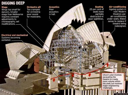
The Sydney Opera House is an example of an acoustical environment that had been conceived in the opposite order to how the venue is applied. This resulted from the initial conditions locked in by visual design 'form following function' in the wrong order. As a visual tourist attraction it is magnificent, but as an autitory entertainment venue it is often critised, as well as needing to be government subsidised.