

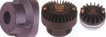
Compression drivers with horns can be approx 20% efficient, approx 108 - 112dB/m/W. The drivers are made in 2 basic sizes.
2in (800 - 8K Hz) 80 - 100 Watts
1in (1K - 10K Hz) 30 - 50 Watts
Horns for compression drivers should not be shortened (truncated) and must be 1 wavelength long at the lowest frequency. Longer wavelengths than the horn length cause the diaphragm to move excessively. The dome diaphragm, unlike a cone, cannot flex with excessive movement and fractures easily. The diaphragm movement is designed to be very, very small and constant across frequencies (constant exertion), unlike a cone speaker. The low frequency limit for large drivers is approx 800Hz - wavelength 18in/440mm.
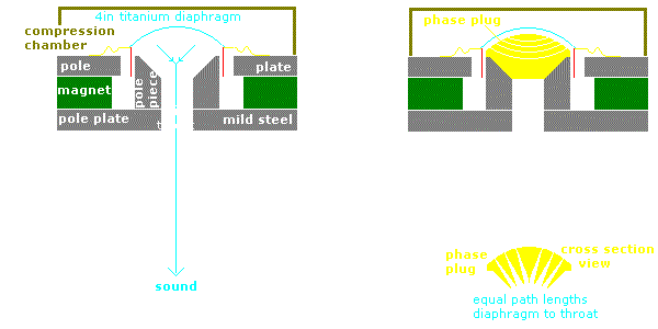
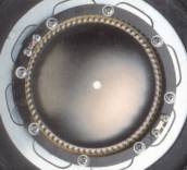
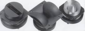
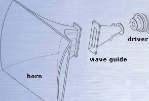
"1in" and "2in" refers to the throat diameter of the horn. Inside the driver is a titanium dome diaphragm instead of a cone. The largest dome is 4in in diameter. The dome is very fragile and should not be touched.
The reverse side of the dome is inside a compression chamber. Sound from the front of the diaphragm passes through a plug with slots (phase plug). The slots direct sound from the dome diaphragm to the small opening (throat) which couples to the horn. The phase plug is very close to the dome. The slots in the phase plug are machined so the acoustical path lengths from the whole dome surface to the throat are identical. At high frequencies above 6kHz, the wavelengths can be smaller than 50mm/2in and would easily cancel each other across the surface of the dome. A large driver may have a 4in diaphragm with the sound compressed through the phase plug to the 2in throat opening.
WARNING! The titanium dome diaphragm is very, very, very fragile and should not be touched.
Compression tweeters
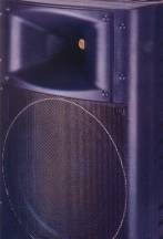
The majority of horn systems are 2-way - one 15in front loaded speaker with one horn. Against marketing and popular belief, compression drivers do not successfully produce energy above 6k - 10kHz. Compression tweeters are rarely used because of cost, and consumer demand for systems is small.
Traditionally, professional sound system PA's are not designed for fidelity. The most common practice with these 2-way systems is to EQ (equalise) boost the hi-frequency energy to the horn, with limited success. The extreme of this practice is with constant directivity horns.
Compression tweeters are approx 106 - 110dB/m/W efficient at 50 - 100 watt. Compression tweeters have always been available but have not been commonly used because of cost. These tweeters are of excellent quality and superior in performance to the majority of domestic audiophile tweeters.
However, the greatest changes have been due to shift of manufacturing to Asian countries. Most speaker, compression driver and compression tweeters are now available at low cost in comparison to earlier times. Build quality can be excellent, but completely disconnected from performance. The modern marketing trend is to provide the greatest variation. Therefore, auditing of performance can be non-existent, resulting in many driver components bearing no relationship between their marketed performance (better or worse) and what they actually do.
Driver protection
For active systems, compression drivers and compression tweeters must not be connected directly to the amplifier. Protection capacitors must be placed in series between the amplifier and compression driver or compression tweeter. The turn on-off pulses and DC offset from the amplifier can easily destroy the diaphragms. The capacitors will also add an extra 6dB of roll-off to the crossover filter slope.

Horn dispersion
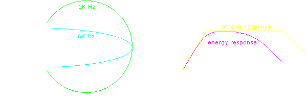
The on-axis response of horns can be flat but can become directional as the frequency increases. The energy response decreases as a function of the polar response. Because the on-axis frequency response can remain flat, no compensation is required for near field listening. To Keep the energy response and frequency response similar for far field listening, frequencies above 3kHz may have to be boosted +6dB . This is a major problem with constant directivity horns. Round horns for sound systems are the most efficient and musical with the least distortion. Musical instrument horns are also round and directional.
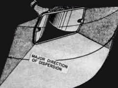
Horns for sound systems are changed in shape to rectangular to increase horizontal dispersion. Changing shape from circular is a compromise that reduces efficiency and causes lobe distortion. Lobe distortion is heard as the peaking and dipping of notes around the horn. Some horn shapes minimise horizontal lobes but increase vertically.
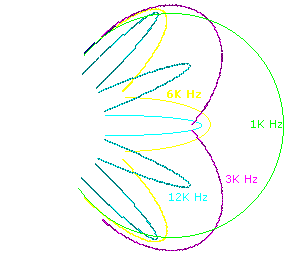
There is a proliferation of questionable various shapes of rectangular horns on the market, all claiming to provide choices for different horizontal dispersion patterns. A simple and essential test for a horn is to put it to your ear as an acoustical telescope. Similar to an optical telescope, there should be no colouration or distortion in the image or sound. Any horn shape other than circular will decrease efficiency and musical performance. There is no exception to this rule. A good horn player would easily hear and not accept any similar compromise made to the bell of their instrument.
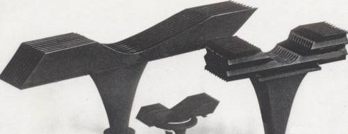
The multi-cell horn was the most common horn for large cinemas until 1960 (at top of page ). These horns were large, very efficient and had consistent wide even energy dispersion. Lobing was limited to the highest frequencies only. Each cell was individually constructed and grouped together form various arrays. Some were lead lined and sand filled, for permanent installations only. This level of engineering can no longer be justified in our modern world of high profit and low cost. These old horns can still be seen in a very few old cinemas and museums.
Constant directivity. In recent times, computing power has enabled horn designers to be very innovative, bending the laws of physics for shortening (truncating) horns, and increasing horizontal dispersion (constant directivity), but with limited success. The professional audio market is driven by trends. When constant directivity horns were first marketed, many senior engineers were jokingly heard saying, "they are not called bum horns for nothing".
The principles behind constant directivity and wave guides are excellent in theory. The wave guide attempts to convert the circular throat opening of the driver to a vertical slot (line-source) at the throat of the horn. A line source is similar to the vertical slot of a water hose nozzle. Paint spray guns and many pressure pack cans use this same principle. The vertical slot causes the water or paint to be spread horizontally.
In practise, a line source wave guide results in loss of efficiency as the frequency increases, which has to be compensated for. Air radiation resistance to the diaphragm becomes nonlinear and the diaphragm is physically stressed with excessive movement at high power, and can easily fracture. This also has to be compensated for by controlling power (peak limiting) to the driver. Overall, the compromises and questionable improvement of horizontal dispersion of constant directivity horns do not match the original circular exponential horn acoustical principles.
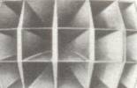
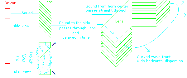
The lens. For circular and near circular horns a lens was the most effective means to increase horizontal dispersion without introducing lobe distortion, and minimises loss of efficiency. An acoustical lens is the equivalent of the optical lens.
A labyrinth of concave plates is put in front of the horn. Sound from the centre of the horn passes through unhindered. Sound to the sides of centre in the horn pass through the lens labyrinth, increasing the distance travelled and delayed in time. The sound waves are bent, forming a wide horizontal dispersion. The lens improves horizontal dispersion as the frequency increases.
The lens is no longer used. It is large, fragile and expensive. Economic rationalism, not technical performance was and still is it's downfall. Also, the lens function was not well understood. It's physical appearance does not give an intuitive understanding of its function. Many old 60's - 70's roadie sound engineers believed the lens directed sound downward to the audience sitting in the front row. The lens was commonly referred to as a waterfall effect speaker. Ignorance and miss-understanding was, and still is, a problem throughout the professional audio industry.